ECL82 vs ECL86 are different tubes no substitutions.
Derek Walton PCL86 (*NOTE: different heater, same tube)
"Therefore, you can use PLCL86 valves with the heaters in parallel or you can use ECL86 with the heaters in series."
You will probably have to substitute transformers, but the layout, wiring, etc. will help.
https://web.archive.org/web/20070106213517/http://www.iol.ie/~waltonaudio/pcl86.html
http://www.r-type.org/exhib/aai0028.htm
Attachments
Last edited:
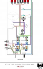
The web archive schematic shows negative feedback with a switch, this schematic shows no feedback. Why?ECL82 vs ECL86 are different tubes no substitutions.
Derek Walton PCL86 (*NOTE: different heater, same tube)
"Therefore, you can use PLCL86 valves with the heaters in parallel or you can use ECL86 with the heaters in series."
You will probably have to substitute transformers, but the layout, wiring, etc. will help.
https://web.archive.org/web/20070106213517/http://www.iol.ie/~waltonaudio/pcl86.html
http://www.r-type.org/exhib/aai0028.htm
View attachment 1066348
ChrisABC,
No negative feedback . . .
That is right - if you are looking for Schade feedback, output transformer secondary to Cathode feedback, or Global feedback, it is not there.
But, there is Local negative feedback:
Triode Wired Mode
Ultra Linear Mode
Note: The schematic in Post # 41:
The Ultra Linear Tap shows more B+ to Screen Turns, versus Screen to Plate turns.
If actually wired that way, a 40% UL tap becomes 60%, and a 25% UL tap becomes 75%.
(Probably the schematic editor did not have a correct model for an actual UL output transformer).
Pentode/Beam Power is 0% Ultra Linear
Triode Wired Pentode/Beam Power is 100% Ultra Linear.
I have used 40% UL tap, 100% Triode Wired Beam Power mode, and 0% Beam Power mode for push pull outputs.
I have used 20%, 50%, 80% UL taps for single ended outputs,
as well as 100% Triode Wired Pentode/Beam Power mode, and 0% Beam Power mode.
Have fun building and listening.

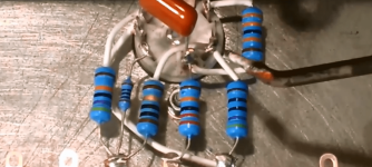
Sorry to dredge up an old thread, but on post 34 of this thread, there is a youtube video and a schematic.
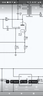
The schematic shows R5 and R6 as being in series between pentode cathode and ground, with a connection between the two going to the triode cathode.
In the video, the author connects R5 to the pentode cathode and earth, and R6 between the pentode and triode cathode, with no connection to R5, apart from the socket terminal (16:10 on the video).
Can anyone enlighten me as to which is correct?
That connexion provides a degree of positive internal feedback.Can anyone enlighten me as to which is correct?
When carefully chosen the result can be zero internal impedance on the amp speaker terminals.
But depending on other circuit constants, in particular the OPT, instability may result.
The amp will also be a lot more sensitive to PS ripple. That hookup should be avoided except by the knowledgeable.
Schade NFB is not a cure all either. Again, such an amp is more susceptible to PS B+ ripple. 😱
Novarria's OPTs are rubbish. Once a friend came to me with one of their kits wandering why it sounded so bad. Hooking up the oscilloscope was enough to show a very poor frequency response and lack of inductance. Because the circuit looked reasonable, I convinced him to open the OPTs up to see what was so bad about them. I can tell with 100% confidence that most power transformers would be way better in the same application! Some schemes might have mistakes. Given the non-educated typical audience they were made for, I don't think that circuit was supposed to be used with positive fbk.
Not yet, I will in the very near futureDid you build this, Patrick?
Sorry, I'm a total novice when it comes to feedback circuits.That connexion provides a degree of positive internal feedback.
When carefully chosen the result can be zero internal impedance on the amp speaker terminals.
But depending on other circuit constants, in particular the OPT, instability may result.
The amp will also be a lot more sensitive to PS ripple. That hookup should be avoided except by the knowledgeable.
Schade NFB is not a cure all either. Again, such an amp is more susceptible to PS B+ ripple. 😱
Which hookup should be avoided?
The one in the schematic, or the one in the video?
@OldHector
I've just gone back to do what you suggest, and realised I've misunderstood what he's done in the video. All is now clear.
I've just gone back to do what you suggest, and realised I've misunderstood what he's done in the video. All is now clear.
@jhstewart9Sorry, I'm a total novice when it comes to feedback circuits.
Which hookup should be avoided?
The one in the schematic, or the one in the video?
Ignore this, it was me being thick.
I'm currently building it as per the video with a 20v laptop power brick and boost converter for HT supply. I've started a thread. Had a few issues, probably down to my lack of experience but I'm getting there. I ended up starting again with another, much simpler schematic using PCl86. I've just stripped it down again to start over with the schematic from the youtube video.Not yet, I will in the very near future
It's a steep learning curve but it's good fun.
I still don't get it. The video and the schematic are different. Which one should be avoided?@jhstewart9
Ignore this, it was me being thick.
Attachments
What are you seeing that's different between the video and schematic? It was R6 and R5 that were confusing me (not difficult) until I looked at it properly.
Just had a look at your thread, you seem to be having some fun and games. I'll let you know how I get on.
Good luck
Just had a look at your thread, you seem to be having some fun and games. I'll let you know how I get on.
Good luck
I still don't get it. The video and the schematic are different. Which one should be avoided?
Hopefully this makes it clearer. Bit of a misleading schematic for us amateurs.
By eyeball, that connexion puts a short across R5. 😱
In some circuits R1 is used to maintain stage gain while the cathode cap across R6 is eliminated.
But as usual, nothing is free. Some of the audio power out that should have been at the
OPT primary is now dissipated in R5.👎
In some circuits R1 is used to maintain stage gain while the cathode cap across R6 is eliminated.
But as usual, nothing is free. Some of the audio power out that should have been at the
OPT primary is now dissipated in R5.👎
Sorry, my redrawn schematic is rubbish, should be this:By eyeball, that connexion puts a short across R5. 😱
In some circuits R1 is used to maintain stage gain while the cathode cap across R6 is eliminated.
But as usual, nothing is free. Some of the audio power out that should have been at the
OPT primary is now dissipated in R5.👎
No, it goes to pin 2 along with R5. It should be as per my last effort with redrawing the schematic.It was R6 for me as well. It seems to connect to a different socket pin in the video.
- Home
- Amplifiers
- Tubes / Valves
- Simple ECL86 amp