What I mean to say is, that the circuit in post #137 is either 100% feedback regardless of the driver plate resistance (and so signal triode or signal pentode does not make any difference and both are inadequate) or the effective value of the feedback resistor depends on beta which in turn depends on the anode resistance of the driver tube.
The Amp in #34 has many Warts & that is what attracted it me too it. I figured one diagram with many switches could cover most possibilities. So here we have Schade NFB included, often creates a disaster as in this example. And Schade does cause yet another problem to be discussed. The internal cathode to cathode Positive FB also deserves a look. This is a real good cct to carefully analyzed before building.
I've built this exactly as per the schematic. It was my first build. I'm really happy with the sound but I really enjoyed building it and will be looking to build more soon. I have a load of PCL86 tubes, could you recommend a circuit with the best possible sound?

Are The PCl86 and ECL86 interchangeable in these designs? I know the heater voltages differ but are the otherwise interchangeable?
That's more theorical than practical. If the effective value of the fbk resistor becomes 2K for the EL84 amp the driver has to provide 2.2 mA peak. That's about its anode current and so distortion will be high anyway, easily double figures. You cannot increase the value of the feedback resistor because you are limited by the power supply. There is no escape.45
A pentode for V2a remains the better option.
On the other end, if one can tune the feedback factor and the effective feedback resistor becomes a more usful value, an appropriate (more linear) triode can be chosen. Again not much practical difference.
What you posted is indeed what I tought. If you put R1=0 and R2>>transformer primary impendance, the feedback factor still depends on the tube anode resistance. With triodes you get higher effective value for RL (i.e. less feedback, which is the general recommendation) and triodes a re more linear, in general.
Last edited:
Yes they are. Some datasheets are more coustious about max ratings for the PCL86 (PCL82) respect to the ECL86 (ECL82) but I think that was dictated by the fact that the PCL variants were meant for heaters in series with one power supply for many tubes (televisions mainly). Ina HiFi amp that is not case, normally.Are The PCl86 and ECL86 interchangeable in these designs? I know the heater voltages differ but are the otherwise interchangeable?
I have tested the PCL86 with anode voltage well above 300V without any problem. In triode mode my amp was running at 350V anode voltage....that's how I could get 2W at about 5% THD without any feedback. Anode dissipation and g2 disssipation, I would not go beyond recommended max ratings.
P.S.
@pl802 Don't forget that in 1937, when the full investigation was made (according to the reference article), many triodes we can use today were not born yet.
It also says that those formulas are only valid for small values of feedback. Now that I know where it orignally comes from, I am going to retrieve the Radiotron handbook and read all the chapter....
Last edited:
I would suggest using E series valves because the 6.3V is pretty standard, and allows flexibility should you want to change the design at all. The P series were intended to run from 300mA supplies, often crudely derived directly from mains through a dropper resistor and feeding all valves in a radio or TV. And in case it hasn't been mentioned, try getting a centre tapped 6.3V heater supply so that the centre tap can be earthed. Usually preferred for push pull designs but if I were to build another valve amp I would always try that.
I have build both ECL82 and ECL86 amplifiers. I chose the supply voltage of 290V so that the cathode to anode voltage was, in the case of the ECL82, about 250V, plus approx. 20V cathode and about another 20V for the voltage drop across the primary of the OPT which had quite a high resistance. That was some time ago, and used a "universal" OPT which RS used to sell. The amps both included some feedback from the output to the triode cathode. I do not have the ECL86 version and I'd have to fetch the ECL82 up from the loft and remeasure it now as I don't have the original info. (these did not have the centre tapped heater line, though).
I have build both ECL82 and ECL86 amplifiers. I chose the supply voltage of 290V so that the cathode to anode voltage was, in the case of the ECL82, about 250V, plus approx. 20V cathode and about another 20V for the voltage drop across the primary of the OPT which had quite a high resistance. That was some time ago, and used a "universal" OPT which RS used to sell. The amps both included some feedback from the output to the triode cathode. I do not have the ECL86 version and I'd have to fetch the ECL82 up from the loft and remeasure it now as I don't have the original info. (these did not have the centre tapped heater line, though).
I've corrected the 6L6 load to 2.5K this time. The bottom line is still the same, the triode gain varies as the load changes.
OTOH the pentode output varies as Gm*Rl so follows the loudspeaker impedance curve.
Bode then for the pentode would be the reciprocal of the triode driver response.
A pentode as a driver is definitionally the way to go. Or drive with SS. Either way the Transimpedance Amplifier results.
The 1938 receiver with the PP NFB 6L6 amp was a Philco, 15 tubes in all! Lots of SW bands. And AFC included, must have been top of the line. 👍
And for those who have the time-
Stabilized Feedback Amplifiers HS Black Bell Telephone Labs Jan 1934
https://ia902703.us.archive.org/24/items/bstj13-1-1/bstj13-1-1_text.pdf
Attachments
Thank you John
Coincidently last week the youtube algorithm spat out H.S Black the man who invented feedback to me.
It was/is a good watch.
btw would you please reference the Transimpedance Amplifier.
Coincidently last week the youtube algorithm spat out H.S Black the man who invented feedback to me.
It was/is a good watch.
btw would you please reference the Transimpedance Amplifier.
An amplifier where the load changes the gain of the driver tube is a no no. Although pentode driver or transimpedance in general can works ok I will continue using my time with something better, possibly without sand....
Thanks for the sims.
Thanks for the sims.
https://www.bing.com/search?pc=U528&q=transimpedance+amplifier&form=U528DFbtw would you please reference the Transimpedance Amplifier.
I'm thinking a 6AU6 would be a good front end for this amp.
I'll have a look in a day or so. 😀
I have another idea about this kind of circuit. Instead of doing it to drive a loudspeaker, I would use it to drive a power pentode that works with 50% cathode fbk. This way a PP OPT could be used for experiment and maybe could also work very well for great HiFi performance.....
A 6L6GC would give almost 11W with 350V anode voltage, 250V g2 voltage and 4.2K load, as per datasheet. The OPT will be 4.2K plate-to-plate. Roughly I think some 180V peak drive would be required.
In reality a small air-gap in the OPT would be necessary to handle the g2 current that only flows through the cathode half but nothing really difficult. It could be fine or would just require to change the interleaving of E's and I's to achieve a bit larger distributed air-gap. It's just 7 mA at max Pout for the 6L6....
Using a 6AU6 + high gm small pentode it should be possible with a bit more supply, say 400-420V. So a small price to pay with separate supply but nothing really bad. Right now I am thinking about a 6HA6 working at 220V plate voltage, 100V g2 for 20 mA anode current. With 10K anode resistor, 220K next stage grid resistor, 420V supply would be needed for about 190V peak output....
https://frank.pocnet.net/sheets/202/6/6HA6.pdf
Of course, there are possibly several other choices in place of the 6HA6 and the double supply might be eliminated but it's not important right now.
Maybe the 6HA6 could be cathode-biased with 2 SiC diodes in series:
https://www.bartola.co.uk/valves/tag/led-bias/
Last edited:
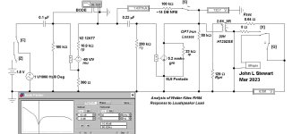
The Split Load Transformer Coupled Amplifier
In Summer of 1999 I put this experimental contraption together, a triode connected 6K6GT driving into a PP OPT with unconnected primary windings. It really needs a gapped core but I made the measurements at One KHz to get around that problem.
Later I stuffed a mu follower in front of it to get some gain. Then took some measurements & wrote a report. I sent that to ED Dell at AudioXpress magazine, the article got published June 2001.
The output lead is taken off the UL tap. With a 600 Ohm load the 6K6GT sees 12K, a very easy load for the tube. Soon after the OPT found its way into a PP 33 Amp.
Attachments

@jhstewart9, the air gap really depends on how much g2 current the power tube draws. Normally, in EI transformers, the natural air-gap can cope with 3-5 mA.
This is the case where 1x1 interleaving of the 'and I's occurs and it's a distributed gap.
Doing an interleaving of 2x2, 3x3 etc. the airgap will increase. This way on can still get significantly higher inductance respect to a SE OT that is gapped for higher DC currents.
This is the case where 1x1 interleaving of the 'and I's occurs and it's a distributed gap.
Doing an interleaving of 2x2, 3x3 etc. the airgap will increase. This way on can still get significantly higher inductance respect to a SE OT that is gapped for higher DC currents.
Here you can find the formulas. The main point is that in the typical butt gapped SE transformer, it is rather difficult to get below a certain air gap size. Say, below 0.1 mm with good accuracy.
Actually if you use a spacer that is not rigid enough you can see the inductance changing while you apply some pressure. So it will also depend on how you finish the transformer and how tight you pack the core....
Actually if you use a spacer that is not rigid enough you can see the inductance changing while you apply some pressure. So it will also depend on how you finish the transformer and how tight you pack the core....
Attachments
- Home
- Amplifiers
- Tubes / Valves
- Simple ECL86 amp