Sorry, maybe I misread, I mean "IC" is labeled to board, not to chip itself. If "C86" is in the chip, maybe this is actually "G86" (from 74AHCT1G86GV)...
I've been practising my soldering skills this morning...
Filter resistors are 8K06.
Next up is careful inspection and test for shorts etc.
Then I need to get a DSD input set up for it and sort out an output arrangement!
With regard to the latter, I'm thinking of using a Broskie Unbalancer configured for I/V, which also offers the option of LP filtering on the inputs.
Onwards
Ray
An externally hosted image should be here but it was not working when we last tested it.
An externally hosted image should be here but it was not working when we last tested it.
Filter resistors are 8K06.
Next up is careful inspection and test for shorts etc.
Then I need to get a DSD input set up for it and sort out an output arrangement!
With regard to the latter, I'm thinking of using a Broskie Unbalancer configured for I/V, which also offers the option of LP filtering on the inputs.
Onwards
Ray
Sorry, maybe I misread, I mean "IC" is labeled to board, not to chip itself. If "C86" is in the chip, maybe this is actually "G86" (from 74AHCT1G86GV)...
No, having looked again I'm convinced it is labelled C86 and 95Z, as perhaps for 74AC86SCX; I'm guessing it'll be some sort of logic device?
Ray
It is perhaps a 8-pin dual 2-Input Exclusive-OR Gate SN74LVC2G86
Check the marking code in page 8 of pdf
http://www.ti.com/lit/ds/symlink/sn74lvc2g86.pdf
Check the marking code in page 8 of pdf
http://www.ti.com/lit/ds/symlink/sn74lvc2g86.pdf
C86 is SN74LVC2G86!
gagnou,
Yes, I'm pretty sure that is what it is. It fits all my measurements and the logic table in the data sheet. This is a clever way to turn the DSD data bit streams into a pair of equal and opposite bit streams with identical propagation delays.
I was looking at D-Flip flops and inverters but found nothing that matched my measurements and circuit function.
The SN74LVC2G86 is available from Mouser.
Thanks for figuring this out.
Just remark:
Nautibuoy
from the picture, You miss to solder some pins on ICs
and Probably some other parts too.
Check it carefully before apply power supply?
🙂
Nautibuoy
from the picture, You miss to solder some pins on ICs
and Probably some other parts too.
Check it carefully before apply power supply?
🙂
Just remark:
Nautibuoy
from the picture, You miss to solder some pins on ICs
and Probably some other parts too.
Check it carefully before apply power supply?
🙂
No, I don't think I missed any and I think they're all good, they look fine under a magnifier. After tacking them in place I used the drag technique with an iron and some flux; there was a good amount of solder on the pads.
That said, I have spent a couple of hours tracking down a short circuit in the 5V Vcc circuit of one channel. I had a solder bridge under one of the decoupling caps.
I've also removed the IC13 & IC14 (SN74LVC2G86) chips to replace them. I thought I might have overheated them and one of the inputs was shorted to ground so decided to remove and try again.
Slowly getting there.
Diff DSC1 board a Troubleshooting nightmate
No problems getting the computer to work with the Amanero.
After first power up only one of the four 32-bit sections is putting out a signal.
The kit design has no test points for troubleshooting - ugh. I am getting 5V and 3.3 volts in all the right places.
My meter probes can easily short IC chip outputs so I am going to have scrape off the solder mask in places so I can measure key signals in transit. What a PITA.
I might use the heat gun to resolder some of the chip leads.
Stick at it carlsor, hopefully it will be worth the effort.
I'm relatively new to smd soldering and I fear a similar result, already evident from the short I built in!
For anyone interested, this video shows the drag technique I used for mounting the ICs on my board;
https://www.youtube.com/watch?v=5uiroWBkdFY
I'm not quite as neat as that guy though.
Ray
I'm relatively new to smd soldering and I fear a similar result, already evident from the short I built in!
For anyone interested, this video shows the drag technique I used for mounting the ICs on my board;
https://www.youtube.com/watch?v=5uiroWBkdFY
I'm not quite as neat as that guy though.
Ray
I'm a 'painting by numbers' sort of chap; I can solder a PCB together and follow a schematic but I don't 'get' circuit theory. When I looked at the pictures of the differential board on ebay I thought it looked like R1, R2 and C25 were defining a LP filter but the component values and presence of R3 mean that doesn't make sense - so what do R1, R2, R3 with C25 do? Just trying to understand.
Ray
Ray
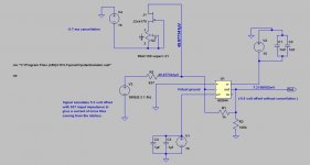
...there's very little to the output section of the differential board, here it is;
An externally hosted image should be here but it was not working when we last tested it.
Make of it what you will.
Ray
Diff DSC1 Working
I am listening to my differential DSC1 right now. The details of my configuration are:
1. DSC1 constructed with provided parts except for using Susumu RG 0.1% 8.06k SMD resistors.
2. Power to DSC1 board is a 2amp Belleson Vreg.
3. Power to Amanero is provided by a Regen module ($175usd) from Uptone Audio which provides a clean 5V USB power signal and also regenerates a cleaner USB signal. I use the same unregulated 8V power supply for both the Belleson and the Regen so no isolator is needed.
4. Output Transformer is a Cinemag DML1-15/15B into a 15K load.
5. Software is JRiver 22 running at 2XDSD DoP using the Amanero Kernel Streaming driver. I couldn't get 4XDSD to work.
My reference DAC is an NOS PCM1794 single layer DDDAC using the same Cinemag DML1-15/15B output transformers. I have a JFET buffer between the DAC outputs and the transformers which gave more impact to the music.
The diff DSC1 sound is crisp and clean with no noise. Comparing this DSD DAC with a highly upgraded/tweaked PCM DAC that has been burned in isn't fair, but here goes. The diff DSC1 reveals less detail and is not quite as impactful as my reference DAC. The music sounds a tad artificial and doesn't flow as well as the ref DAC. Percussive leading edges sound a bit blunted. Of course there is some new parts sound. Run time and more changes may improve the SQ considerably.
The next things for me to try with the diff DSC1 is to use Signalyst software which can hopefully run at 4XDSD. I also plan to put a JFET buffer between the DSC1 outputs and the transformers.
Noise
cu6apum
Noise was never a problem for me, at least at levels that are noticeable from my listening chair between tracks. Maybe the Susumu RG 0.1% 8.06k SMD resistors are preventing one potential source of noise. I also use top quality Vregs and a cleaned up USB signal which may also help.
cu6apum
You say you have defeated the noise?!
Noise was never a problem for me, at least at levels that are noticeable from my listening chair between tracks. Maybe the Susumu RG 0.1% 8.06k SMD resistors are preventing one potential source of noise. I also use top quality Vregs and a cleaned up USB signal which may also help.
Good that you got it up and running Carlsor and I'm sure it'll get better as you run it in.
What's the output level like?
That's why I'm pondering an active tube based output stage like the Broskie Unbalancer (instead of transformers).
Ray
What's the output level like?
...is not quite as impactful as my reference DAC. The music sounds a tad artificial and doesn't flow as well...
That's why I'm pondering an active tube based output stage like the Broskie Unbalancer (instead of transformers).
Ray
Last edited:
This is the key problem of this dac, as I'm assembling the second proto. You don't hear it, or you just ignore it? Is it lower with balanced version? I doubt so, according to the modus operandi.cu6apum
Noise was never a problem for me, at least at levels that are noticeable from my listening chair between tracks. Maybe the Susumu RG 0.1% 8.06k SMD resistors are preventing one potential source of noise. I also use top quality Vregs and a cleaned up USB signal which may also help.
Hello all.
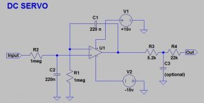
This is for those of you who are interested in removing the 2.2 Uf coupling cap between the AD844 and the following stages in the original DSC1 and killing the voltage offset.
1. I used a Jfet, trimmer pot and cap tied to the negative rail of the AD844 (I use +and- 15 Volt rails.) This method was suggested in the excellent EUVL thread below.
http://www.diyaudio.com/forums/digital-source/195483-zen-cen-sen-evolution-minimalistic-iv-converter.html
Look at page 17 Post 170 for an explanation.
This got rid of most of the offset but drifted from -150 mv or so to hover around +20 mv after about half an hour. I use the Lsk 170s because I had them. You could use the Lsk 147 or experiment with other low noise jets.
There was still too much offset, so I used DC servos between pin 2 of the LME49720s and the output end of R805/R815. See circuit below. The OP amps I used were Lf411 because I had quite a few of them and tested a few for lowest inherent offset. You could use other more modern OP Amps . See the servo link.
If you want to read all about DC servos, check this out.
http://www.diyaudio.com/forums/chip-amps/107246-dc-servo-question-5.html
The changes have worked out very well, with offset within 1 or 2 millivolts.
More importantly, the sound has improved!
Just to cap off, I should say that I use Jung super regulators for all stages except the 3.3 volts that runs the output relays. USB is powered from another Jung 5volt regulator inside the chassis over a modified USB cable.The Amanero uses an isolator chip as suggested in their website.
I use a Mac Mini running Windows 7 with Bootcamp. The Mac Mini has an outboard linear supply. I use the Signalyst player for critical listening and JRiver for ease of use.
In other words, I am happy with the sound and grateful for Jussi's great DAC.
I hope this is useful to some of you.
Cheers
Attachments
Diff DSC1 Comments
OUTPUT LEVEL: The output level sounds about the same as my Reference PCM DDDAC. It is strong enough that I can use my LDR volume control without an additional gain stage. Theoretically, the maximum voltage across the differential outputs is near 5 volts.
NOISE: I carefully listened for noise between tracks before I answered your query. What I can't hear is not a problem for me.
Circuit checkout suggestion: The outputs for each channel should measure <=0.2mv DC across the + and - Outputs with music playing. If not, check the soldering of all the outputs from the bit shift ICs through the resistors.
My intuition tells me that the differential DCS1 should sound better than the single ended version. I suspect that there is some cancellation of bad audio artifacts by the differential circuit. Also, the differential signal path has far fewer components. I never bought a SE DSC1 so I do not have direct experience with it.
Thanks for this Carlsor and I'll use your checkout suggestion when I come to power mine up.
The output is healthy enough for my purposes and has got me thinking that a simple unity gain differential to single-ended buffer should suffice for my output. I pencilled in the Broskie Unbalancer thinking I would need its first stage gain for I/V.
The parts to finish assembling my Differential DSC-1 board arrived yesterday so will try to check it out and power up over the weekend. In the meantime, I've been concentrating on the ElectrArt DSD Principle board; I spent a lot of time soldering on 805 size bypass caps that the original builder omitted (so fiddly when the rest of the board has ben populated!) but hope to have it working shortly.
Ray
Last edited:
NOISE: I carefully listened for noise between tracks before I answered your query. What I can't hear is not a problem for me.
Between tracks DCS1 is as silent as chip noise can be. Different story is when useful music signal and some noise is combined, only then modulated noise is occured. Note, if music signal is strong enough, all is ok. If music level is below -35dB and down to let's say -60dB, then very specific (and nasty in my ears 🙂) noise is heard with music. If DSC1 playing silence (as between tracks), all is ok.
Classical music has sometimes such low level passages. Now, if someone wants to ripp vinyl to DSD, then he get's always low level surface noise just about between -55 to -65dB, so very probably all intros and outros of tracks are affected. Don't blame DSD as format for that, with format all is good.
Last edited:
- Home
- Source & Line
- Digital Line Level
- Signalyst DSC1