I changed R1/R2 500ohm resistors to 1k, this correlated noise as cu6apum noticed, are there as before.
I know this is a Signalyst DAC thread but I thought these links might be of interest as they're closely related. It's a 32tap FIR board that was available from a Japanese vendor (it's no longer available).
Google will translate it for you.
DSD????
http://yanasoft.jp/yana/DSD_DAC32 2_0.pdf (you don't need to translate the PDF, if you do it will be scrambled).
The interesting thing is that it mentions passing the output of the FIR filter to transformers, but I haven't found any more info on that yet other than this thread;
Pure DSD DAC (DAC Less)
Ray
PS. It's just clicked that 'Flowerpot', responsible for the xtremeplace thread above, has been contributing on the 'Best DAC' thread;
http://www.diyaudio.com/forums/digital-line-level/273474-best-dac-no-dac-159.html#post4833565
Last edited:
Both designs you cited are using non-rect window filter. I'm highly concerned, whether should I try to calc the same for Jussi's board, or keep trying with equal resistor values.
The prob is that I don't have access to a good spectrum analyzer and thus can't define the source of this noise.
If it's HF feedthrough, nothing can beat it but proper filter design (yes, non-rectangular window) and PCB layout. Maybe band-limiting galvanic decoupled audio transformers in addition.
If it's a side effect of DSD idle tones, nothing can help, need to implement an own SDM engine fixing those DC issues. The latter will doom the project as I feel too weak in FPGA programming yet.
Further to my earlier post, there is some information about the ElectrArt DSD Principle board on their Blog (translation will be required);
ElectrArt Blog
Check out the blog entries for October and November 2012, the latter has info, which I don't understand yet, about the FIR filter calculations but it may be more meaningful to some of you here who are better at this sort of thing.
The reason I've been digging into this a bit is because I've just purchased a used ElectrArt DSD Principle board, for which this is the schematic;
http://fpga.cool.coocan.jp/electrart/FIRTST.pdf
Ray
Last edited:
Ray,
This is 8-bit filter whilst we have 32 bit. Need to do some math fixing the values.
If this is the case. If.
This is 8-bit filter whilst we have 32 bit. Need to do some math fixing the values.
If this is the case. If.
This is 8-bit filter whilst we have 32 bit...
Yes, I'm not so stupid as to not appreciate that. As the information loosely relates to this project I just thought I would share it.
Yes the electrart is only 8 bits filter, but there is a opamp base LPF at the next stage with the balance signal combined to SE at the last stage...
The opamp can be easily change to improved the sound... im using dual LME49710 for the LPF and the burson opamp for the last stage...
in fact you can even tap out the signal from R53-R56 to your own output stage if you wish...
i change all the 8 bit smd resistors and some of the resistors, i removed the coupling caps C36 and C37 since no DC was present...
the 8 bit board sounds better than the 32 bit and it has becomes my reference... you will be surprise how good this 8 bit board sound... those who heard it was very surprise as well...
my next project involves using the BBB/Botic for 512DSD direct output to either the spare sowter transformer that i have or the yana 32tap filter after i tested both to see which sounds better ,i create sort of a cape for the BBB with isolation and reclock, but not tested yet, still waiting for some parts to arrived...
also take this opportunity to thank Ray for sharing his BBB image... once i get all the parts ready i will try out the BBB/Botic direct DSD out...
Google will translate it for you.
DSD????
http://yanasoft.jp/yana/DSD_DAC32 2_0.pdf (you don't need to translate the PDF, if you do it will be scrambled).
The interesting thing is that it mentions passing the output of the FIR filter to transformers, but I haven't found any more info on that yet other than this thread;
the 32 tap board is current output, so there is i/v resistor tie to transformer, the transformer is not a must, its just a recommendation... i go with using the transformer because its proven. i had another friend who recently just built the same 32 tap filter using his own i/v output stage and it works as well...
Yes the electrart is only 8 bits filter, but there is a opamp base LPF at the next stage with the balance signal combined to SE at the last stage...
...the 8 bit board sounds better than the 32 bit and it has becomes my reference... you will be surprise how good this 8 bit board sound... those who heard it was very surprise as well...
Thanks for chipping in Flowerpot. I have seen your positive comments about the ElectrArt elsewhere, which is why I purchased the used board.
Might the balanced operation of the 8 tap board be an aspect of your preference for it?
The opamp can be easily change to improved the sound... im using dual LME49710 for the LPF and the burson opamp for the last stage...
in fact you can even tap out the signal from R53-R56 to your own output stage if you wish...
i change all the 8 bit smd resistors and some of the resistors, i removed the coupling caps C36 and C37 since no DC was present...
I was thinking along similar lines, replacing the op-amp in the final stage with a discrete op-amp like the Burston. and removing C36/37. I am also contemplating replacing the final op-amp with a tube buffer - like the Broskie BCF (which will do the balanced to SE conversion) - by hooking in straight after C40/41.
my next project involves using the BBB/Botic for 512DSD direct output...
My direction of travel is the same, DSD512 seems to work with the BBB/Botic. I plan to use a spare Acko SO3 for reclocking/isolation, though that gives me a slight issue as the ElectrArt board has isolation on its input, which will compromise the SO3 output quality so I need to work out a way to bypass it and add some UFL connectors.
One thing to be aware of, if you're not already, is the Botic doesn't provide a mute trigger. I have asked miero to include it in a release of Botic but haven't seen any sign of it being added yet.
the 32 tap board is current output, so there is i/v resistor tie to transformer, the transformer is not a must, its just a recommendation... i go with using the transformer because its proven. i had another friend who recently just built the same 32 tap filter using his own i/v output stage and it works as well...
I don't have a 32tap Yana board and they are no longer available but, (based on a very quick comparison of the schematics late last night, so I may be wrong), it appears that the Chinese DSC1 boards could perhaps be repurposed in which case the balanced board might be ideal.
also take this opportunity to thank Ray for sharing his BBB image... once i get all the parts ready i will try out the BBB/Botic direct DSD out...
You're very welcome, sharing is what this place is all about.
Ray
This correlated noise is depending heavily from IV stage. We can output even only that noise, without any useful audio signal (for study).
ElectricArt has similar to DSC1 IV stage (yes, balanced version) and there is one difference - R1/R2 has parallel capacitor 2200p (and R1/R2 is 820 ohms, not 500 ohms or 1k but this is not so critical).
In DSC1 such added capacitor causes that AD844 started slowly generation. So I changed AP844 to LME49710. Natural noise floor is lower, but also gain. And correlated noise is lower, but somehow this combination is less prone to other noises and music is not so beatiful as with AD844.
Jussi says that for DSD64, cutting down half of flipflops is good (doing that we need cut signaling to Pin13 for 2 last registers, used already for mute if DSDOE is missing). Also, cut-off point of the analog filter is needed to move from 100kHz (as designed) to 50kHz.
I not followed that route (yet), because correlated noise occurs in my board in every format - DSD64 to DSD512 AND Tascam has zero problems playing "affected" file. This means, conversion quality is actually ok and not depending from actual format.
I made a "sweep", where instead constant level, frequency is constant, and level changes from floor to 0dB and back. And I see from FFT that "correlated noise" start rising, when audio signal fades to -35dB, max is ca -50dB region and it stops after -65dB.
Thats why modern music is so good - level never goes so low. Classical music is different story then.
Might the balanced operation of the 8 tap board be an aspect of your preference for it?
the yana 32 tap has a balanced output... the SQ of the 8 tap and 32 tap actually is very close, the 32tap is without a output stage, just the flip flops driving the transformer, the 8 tap with the opamp output is just a little more dynamic...
My direction of travel is the same, DSD512 seems to work with the BBB/Botic. I plan to use a spare Acko SO3 for reclocking/isolation, though that gives me a slight issue as the ElectrArt board has isolation on its input, which will compromise the SO3 output quality so I need to work out a way to bypass it and add some UFL connectors.
yes the electrart has the additional isolation chip which is not needed actually, the new yana boards has the isolation chip removed. my suggestion is to get the board to work first before you remove the isolation chip...
the electrart do have the mute built in, but doesn't work that well when i try it with the amanero, i just live with it. I just mute at the preamp during the start of the first song, subsequence songs as long as you pause will not have the pop sound, this will work when u fixed the output sampling rate...One thing to be aware of, if you're not already, is the Botic doesn't provide a mute trigger. I have asked miero to include it in a release of Botic but haven't seen any sign of it being added yet.
i think he just sold out all the available board, i already got 2 of the older version, i am very sure he will have a new version of the board very soon... only problem is he does not sell outside japan.... i got the board through a friend who is able to get it from Japan...I don't have a 32tap Yana board and they are no longer available but, (based on a very quick comparison of the schematics late last night, so I may be wrong), it appears that the Chinese DSC1 boards could perhaps be repurposed in which case the balanced board might be ideal.
the electrart do have the mute built in
...
The problem is that Botic doesn't currently have a 3.3V mute output to trigger the ElectrArt's mute function.
i think he just sold out all the available board, i already got 2 of the older version, i am very sure he will have a new version of the board very soon... only problem is he does not sell outside japan.... i got the board through a friend who is able to get it from Japan...
Perhaps you'll put a word in for me with your friend in Japan?
Coincidentally, my differential DSC1 board finally arrived from Japan today. I will try to sketch out the schematic of the output section when I get a little time.
Ray
my differential DSC1 board finally arrived from Japan today. I will try to sketch out the schematic of the output section when I get a little time.
Ray
This interest me a lot, actually.
Of course, I meant to say that my differential DSC1 board arrived from China...
Anyway, there's very little to the output section of the differential board, here it is;
Make of it what you will.
Ray
Anyway, there's very little to the output section of the differential board, here it is;
An externally hosted image should be here but it was not working when we last tested it.
Make of it what you will.
Ray
Diff DSC1 Kit
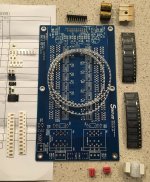
Attached is a picture of the Differential DSC1 kit parts. Seems to include everything except the output transformer and Amanero. Unbelievable for less than $50usd including shipping.
No semiconductors after the bit shift IC's - only film caps and resistors. Front end has logic chips and maybe some voltage changing IC's.
Only paper work is the BOM without IC function explanations. No Schematic.
PCB is tinned so maybe I only have to heat the IC pins on the pads without adding a glob of solder of my own. Some IC pins smaller than SOIC. Circuit trace not visible on bottom.
I still will buy 0.1% Susumu RG 3216 resistors for the shift registers, otherwise I will use provided parts.
Attachments
The Chinese DSC1 boards assume the use of an Amanero board as their input but I plan to use a Beaglebone/Botic with isolator/reclocker using ufl connectors.
I've made some small PCBs to reconfigure the inputs of the DSC1 boards, equipped with three UFLs for the DSD L/R and clock signals and with an isolator for the mute/DSD triggers.
The pictures below shows the DSC1 input board, along with a PCB for interfacing the reclocker to the Beaglebone.


I have 4-5 of the interface boards (unpopulated) spare if anyone wants one for the cost of the postage.
Ray
I've made some small PCBs to reconfigure the inputs of the DSC1 boards, equipped with three UFLs for the DSD L/R and clock signals and with an isolator for the mute/DSD triggers.
The pictures below shows the DSC1 input board, along with a PCB for interfacing the reclocker to the Beaglebone.
I have 4-5 of the interface boards (unpopulated) spare if anyone wants one for the cost of the postage.
Ray
Diff DSC1 Kit Started
I started soldering the parts on the DSC1 board today since I am retired. The kit is mostly SMD components. Two of the parts are tiny 8-pin IC chips which have much smaller pin spacing than the SOIC. Furthermore, these are called a "C86" which I could not find at Mouser or anywhere on the internet. Too bad such small obscure parts were used in this design. I could identify all the other parts which I could get from Mouser if I lost or damaged one.
I had to use solder for each SMD pad connection because the tinned PCB did not have enough solder on the pads. I also used flux on the pads to get better solder flow. Only persons with extensive SMD soldering experience should attempt to build this kit.
I initially only installed four 74AHCT595 bit shift chips with 2 output resistors on each making it a 2-bit differential DSD filter. I want to make sure a DSD signal makes it all the way through the DSC1 before I go to the trouble of installing all the provided parts or purchasing better resistors and caps. If the C86 chips don't work, then this project is kaput.
I started soldering the parts on the DSC1 board today since I am retired. The kit is mostly SMD components. Two of the parts are tiny 8-pin IC chips which have much smaller pin spacing than the SOIC. Furthermore, these are called a "C86" which I could not find at Mouser or anywhere on the internet. Too bad such small obscure parts were used in this design. I could identify all the other parts which I could get from Mouser if I lost or damaged one.
C86 is identified as a 5-pin exclusive-or gate 74AHCT1G86GV.
http://www.nxp.com/documents/data_sheet/74AHC_AHCT1G86.pdf
- Home
- Source & Line
- Digital Line Level
- Signalyst DSC1