Hello Tibi,
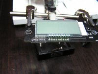
I separated the controle board from the LCD board and use connectors on both boards for the wirering. I measured all contacts in order 1 to 6 with my multimeter on "beeb". Firering up the cd player it reeds TOC but does not respond to the control board. If I press CD door it responds and reads TOC, but if I want it to play, nothing happens. I feel like an nono and don't know how to proceed. Please help.
Robert
PSU issue
Have played for almost a week now and I like it very much.
I decided to change the regulator for the PSU but now I have problems.
With the 7808 I did have 8.01 volt very neat but now I have changed to LT1085 (in principle the same as 1086), I did not have 120 ohm and 680 ohm SMD home but fixed this with 0.25W resistors neatly mounted and I added a 220 uF tantalum instead of the 47 uF (it was just laying there in front of me saying -"pick me, pick me") but now I get 15.25 volt out ????
In I have 12 - 0 - 12 volt and in reality I have 12.15 so peak to peak it is about 25.3 volts AC, but 15 volt DC out.
Where did it go wrong? Do the cap affect the voltage or is it something else? It should not matter if using SMD or not so where did it go wrong? I have not touched anything else on the PSU board. I have been looking around in the thread for the schematics for the PSU cause I have seen it here but now I don't find it.
Last edited:
Mea Culpa
I was almost wrong but just a little right, 1085 is not adjustable unless the are ordered as "adjustable" so the 1085 I had at home are fixed voltage so, no good!😡
I go back to the 7808 for the moment but will order some 1086 to have at home for future use.😉
Thank you Tibi for the schematics.
I was almost wrong but just a little right, 1085 is not adjustable unless the are ordered as "adjustable" so the 1085 I had at home are fixed voltage so, no good!😡
I go back to the 7808 for the moment but will order some 1086 to have at home for future use.😉
Thank you Tibi for the schematics.
Non-adjustable ones have two numbers after LT1085-xx
LT1086CT <<<<<<<<<<<<<< adjustable
LT1086CT-2.85 <<<<<<<<<<< fixed
LT1086CT-3.3 <<<<<<<<<<< fixed
LT1086IT<<<<<<<<<<<<<< adjustable
LT1086IT-5 <<<<<<<<<<< fixed
LT1086IT-12 <<<<<<<<<<< fixed
LT1086CT-3.6 <<<<<<<<<<< fixed
LT1086CT-5 <<<<<<<<<<< fixed
LT1086CT-12 <<<<<<<<<<< fixed
Regards,
Tibi
LT1086CT <<<<<<<<<<<<<< adjustable
LT1086CT-2.85 <<<<<<<<<<< fixed
LT1086CT-3.3 <<<<<<<<<<< fixed
LT1086IT<<<<<<<<<<<<<< adjustable
LT1086IT-5 <<<<<<<<<<< fixed
LT1086IT-12 <<<<<<<<<<< fixed
LT1086CT-3.6 <<<<<<<<<<< fixed
LT1086CT-5 <<<<<<<<<<< fixed
LT1086CT-12 <<<<<<<<<<< fixed
Regards,
Tibi
Hi Tibi,
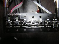
Attached various pictures.
I measured signal between pins LCD and corresponding pins on contol board. They all connect. I don't know if pins make the right contact with the board.
Can I measure that in some way?
Regards,
Robert
Attached various pictures.
I measured signal between pins LCD and corresponding pins on contol board. They all connect. I don't know if pins make the right contact with the board.
Can I measure that in some way?
Regards,
Robert
Attachments
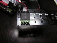
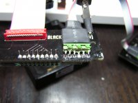
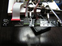
I think you have a shortcut between first two pins, from left, on display side.
Regards,
Tibi
Regards,
Tibi
I noticed the picture was confusing, checked it afterwards. There is no shortcut between first two pins.
Regards,
Robert
Regards,
Robert
Unless is a soldering issue, or some wire do not make contact, I see no reason this do not work.
Regards,
Tibi
Regards,
Tibi
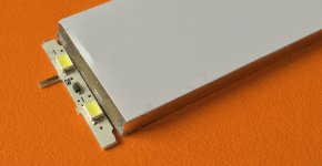
1.) Checking the bachlight I noticed that one pin from the backlight is loose. The pin is correctly soldered to the board but it is loose on the backlight side. How should I fix that?
2.)The connectors I soldered to the boards and the wires connected to them give a signal when I measure them with a multimeter. If I'am correct the switches on the board are triggerd by current. So shouldn't I be able to measure the current to these switches?
Regards,
Robert
2.)The connectors I soldered to the boards and the wires connected to them give a signal when I measure them with a multimeter. If I'am correct the switches on the board are triggerd by current. So shouldn't I be able to measure the current to these switches?
Regards,
Robert
Hi Robert,
1. Backlight have no pins. It is just a small piece of PCB with two leds stuck to a plexiglas. The "pins" are made of PCB as well. If is loose, than the plexiglas was forced and need to be glued again.
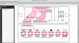
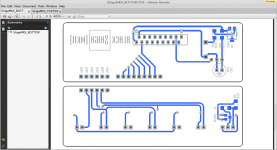
2. Switches are connected on a matrix. I have attached PCB top and bottom traces. Follow traces and see which solder point does not make contact.
Brgds,
Tibi
1. Backlight have no pins. It is just a small piece of PCB with two leds stuck to a plexiglas. The "pins" are made of PCB as well. If is loose, than the plexiglas was forced and need to be glued again.
2. Switches are connected on a matrix. I have attached PCB top and bottom traces. Follow traces and see which solder point does not make contact.
Brgds,
Tibi
Attachments
Last edited by a moderator:
HI Tibi,
Replaced IC's still no go. Was doing LA6541 and I realized I had a LA6541NH which looks the same except 4 NC pins next to smaller Gnd tab. They align over gnd pad so can be lifted out of way. I attached specsheets I think for both. I also can wait for regular LA6541. Also do switches have an orientation on CD door pcb to work right? Thanks!
best regards,
Steve
Attachments
Hi Steve,
You may use LA6541NH, pins 7,8,21,22 are NC-not internally connected and you can solder them to gnd tab. Switches must be horizontally mounted - pins left-right - to work.
Regards,
Tibi
You may use LA6541NH, pins 7,8,21,22 are NC-not internally connected and you can solder them to gnd tab. Switches must be horizontally mounted - pins left-right - to work.
Regards,
Tibi
Thanks Tibi on IC info! So according to button spec sheet schematic I have top pads as one leg and bottom pads as one leg and they connect with button switching. Also I attached V1-4 info from instructions to double check I have done correctly. Thanks!
best regards,
Steve
best regards,
Steve
- Home
- Source & Line
- Digital Source
- Shigaclone MKII Black - The builders Thread