Round 2 from Steve
Attachments
-
 P1010586.JPG652.7 KB · Views: 385
 -
 P1010595.JPG612.7 KB · Views: 134
 -
 P1010594.JPG652 KB · Views: 128
 -
 P1010593.JPG682.9 KB · Views: 128
 -
 P1010592.JPG679.5 KB · Views: 120
 -
 P1010591.JPG642.3 KB · Views: 117
 -
 P1010590.JPG643.4 KB · Views: 321
 -
 P1010589.JPG693.7 KB · Views: 342
 -
 P1010588.JPG605.6 KB · Views: 343
 -
 P1010587.JPG632 KB · Views: 366
Final stills from Steve
Attachments


Hi Tibi and any other builders,
So I can use my motor cable and a bench DC power supply and all motor functions work so...pin 1-2 to the spindle from pcb and pin 5-6 stop[return] function from pcb are not functioning. Pin 3-4 gear drive is functioning. I have datasheets for 3 main IC's but I'm not really sure where to start troubleshooting, any suggestions would be greatly appreciated. Thanks!
regards,
Steve
Hi Tibi,
So I was just reading 2012 SHIGA CD manual as posted in google docs. I have not removed any ferrite beads for separate power to V1-4. I am not sure exactly which have to go as I have V1/V3 on separate and V2/V4 on miniregs. It seemed to be saying if V3 is separate all others have to be also. V1 no L2, V2 no L3, V3 no L5, V4 no L4/L5. Can you confirm if I can do this and which ferrites go. Thanks
best regards,
Steve
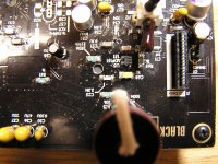
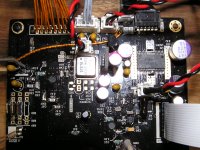
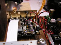
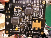
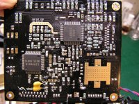
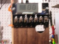
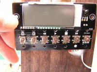
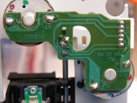
Yeah another post from me. Pin 1 on my motor is SP+ [see photo] not Gnd or SP-. Which is correct for spindle direction? Sorry for all the post but I am really frustrated with myself for not being able to get CD running. Thanks for being understanding.
best regards,
Steve
best regards,
Steve
Attachments
Steve,
Sorry for late replay. One of my very good friends passed away last week.
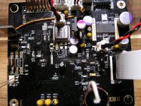
You forget to remove L9, L5, L2 and L3. Therefore the chips took an over-voltage at 8V. With some luck these may still work ...
Regards,
Tibi
Sorry for late replay. One of my very good friends passed away last week.
You forget to remove L9, L5, L2 and L3. Therefore the chips took an over-voltage at 8V. With some luck these may still work ...
Regards,
Tibi
Last edited by a moderator:
Hello Tibi,
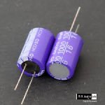
For C43 I ordered a Sanyo Oscon 1000 uF 16V SA (see attachement), before I noticed your discussion with Christoph (page 172 and on). Can I use this cap or should I order a 16SEPF1000M Panasonic instead?
Regards, Robert
Robert,
Sanyo Oscon 1000 uF 16V SA will work just fine.
Brgds,
Tibi
Hello Tibi,
You suggest 1nF 500V Silver Mica across Tentlabs power pins. Can you please indicate those pins or better show a picture of the underside of the board with the cap.
Regards,
Robert
Later today, I'll add a picture.
Regards,
Tibi
Tibi,
Sorry about your loss...
So L1and L4 stay? Can you point me to a more recent document other than the google doc from pre black shiga assembly. It has other instructions than this. I just want to be sure about what I do next. Thank you for your time.
best regards,
Steve
Sorry about your loss...
So L1and L4 stay? Can you point me to a more recent document other than the google doc from pre black shiga assembly. It has other instructions than this. I just want to be sure about what I do next. Thank you for your time.
best regards,
Steve
Tibi,
Before I power up again to see what happens. I have Salas RD's on V1 and V3 and Vicol mini-regs on V2 and V4 so I removed L2-3-5-9 and left L1-L4.
regards,
Steve
Before I power up again to see what happens. I have Salas RD's on V1 and V3 and Vicol mini-regs on V2 and V4 so I removed L2-3-5-9 and left L1-L4.
regards,
Steve
Hi Tibi,
Well no miracle yet but I think trashed my motor cable and I am waiting for some new connectors to arrive. I had a 2 pin connector to play with and I can drive laser motor with 3-4 but will only stop when CD door button is pressed and held. When released it over drives away from disc spindle and won't stop. Still no spindle spin 1-2 pins out. If I use pins 3-4 out to 1-2 at motor spindle spins. If worse case scenario will board tolerate hot air rework to remove damaged IC's? Thanks again for help
regards,
Steve
Need some help!
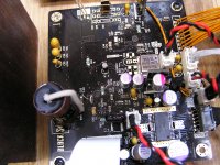
Hi all, some time ago I recived my Shiga and now I have had time to set everything up on a temporary board to test it and let it burn in but I have some problem occuring here.
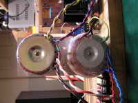
I took an transformer I had in house, 12-0-12 volt 1.5 Amp so it should do even if the regulator will run a little hot but with a bigger sink it should be ok.
Connected the PSU and I had stable 8.01 volt without connecting to main board so I did continue the connection.
Started up the Shiga and the motors are running but I get no TOC reading.
It start running in five sequenses with stop about a second in between and and then come up with dubble zero in the LCD. I have gone through the thread here about 3 times to get some idea, so I have checked the motor cable and connections and there is nothing wrong.
Checked all cables for any dents and nicks but they are ok.
When I connected the main board I have stable 7.99 volts from the PSU and I get the same reading when checking the pad feeding the V1-V4 regulators so I have full voltage to the main board.
I have checked the laser and there is something fishy cause the laser head should be moving up/down but it is dead. The sled is moving to position trying to search but the laser head doesn't move to focus. I checked the laser with my phone and I can not see any laser light and I have tested before on other Players so I know that the camera would catch any laser light but here it is dead.
The motor cable (J2) is giving pin 2, 4.960 V and pin 3,4 give 3.480 V and pin 5, 6 give 3.591 V and at the motor board I have about the same readings.
I really don't know where to go from here but I want it running cause it is not funny to start modding without knowing what it sound like before changing anything.
Anyone who have an idea what to do next?
Hi all, some time ago I recived my Shiga and now I have had time to set everything up on a temporary board to test it and let it burn in but I have some problem occuring here.
I took an transformer I had in house, 12-0-12 volt 1.5 Amp so it should do even if the regulator will run a little hot but with a bigger sink it should be ok.
Connected the PSU and I had stable 8.01 volt without connecting to main board so I did continue the connection.
Started up the Shiga and the motors are running but I get no TOC reading.
It start running in five sequenses with stop about a second in between and and then come up with dubble zero in the LCD. I have gone through the thread here about 3 times to get some idea, so I have checked the motor cable and connections and there is nothing wrong.
Checked all cables for any dents and nicks but they are ok.
When I connected the main board I have stable 7.99 volts from the PSU and I get the same reading when checking the pad feeding the V1-V4 regulators so I have full voltage to the main board.
I have checked the laser and there is something fishy cause the laser head should be moving up/down but it is dead. The sled is moving to position trying to search but the laser head doesn't move to focus. I checked the laser with my phone and I can not see any laser light and I have tested before on other Players so I know that the camera would catch any laser light but here it is dead.
The motor cable (J2) is giving pin 2, 4.960 V and pin 3,4 give 3.480 V and pin 5, 6 give 3.591 V and at the motor board I have about the same readings.
I really don't know where to go from here but I want it running cause it is not funny to start modding without knowing what it sound like before changing anything.
Anyone who have an idea what to do next?
TIC37,
I suggest you to check laser protection bulb. Please remove this with an ESD safe soldering station.
Regards,
Tibi
I suggest you to check laser protection bulb. Please remove this with an ESD safe soldering station.
Regards,
Tibi
Last edited by a moderator:
- Home
- Source & Line
- Digital Source
- Shigaclone MKII Black - The builders Thread