The question with this feedback idea is what does it give us. One thing I have learnt from this is I should make myself my fake 211 driver idea as I have all the parts and I have never seen it bettered. It has SE spectrum with PP DC conditions. I only have 43% UL with parts I have and will have to try it as a new idea. I doubt I will use loop feedback. It migh work with my old Magnepan SMG'a as they claim a purely resistive 4R load.
What could work is UL output and pentode in. It might need some shunt input feedback to make a nicer spectrum. 1% THD 12 watts is the target with 0.3% 5 watts.
The design would tollerate one sided Schade. I shudder at the idea, if it works then why not? Notice the valves were badly mismatched. When matched it was slightly better. The whole idea was to use a cheaper transformer. Mild DC imbalance might promote a better sound as it is a bias of the BH curve like old tape recorder DC bias.
The CCS's were to be certain what was possible. As transistors are highly linear as CCS's I feel they are a good thing. The 3 diodes are to make them as near a resistor with current gain as I can get. If not slightly more second harmonic. The BD139 exactly as a LM317 if so. One feels a BD139 must be a better choice if bolted to the chassis.
Can anyone recomend a cheap triode for this use? My hunch is it will be hard. A double ECC81. I doubt it would be as linear. It will need to swing about 60 Vrms ( think I saw 77 Vrms into a dummy 470K load ). If my notes are right the gain is about 28 for the triode stapped EL84. There is a warning that 7199 is not suited for use below 100 mV rms in when audio use. I think the EL84 would be similar. My notes aren't always as good as I would like for the forum. Please forgive. I tried distruction testing the MJE350. The two constant current actions of it and the EL84 always pevented anything bad happenining. Whilst I can not say it can't be broken I doubt it would have a problem. Note, I go as far as one would dare with the MJE350. With a 211 in SE I suspect a pentode EL84 curve would be better. BTW, EL84 is one of the best sounding valves I know of. It also is good from many makes.
The PSU was a 600V N type MOS FET as a capacitance multiplier. It adds a very small amount of second harmonic.
This is another way of doing plate to grid...🙂
E-linear from a Dynaco ST-70 | Audiokarma Home Audio Stereo Discussion Forums
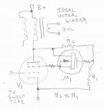
Pentode LTP and the power tubes all fed B+ through the OPT CT.
cheers,
Douglas
E-linear from a Dynaco ST-70 | Audiokarma Home Audio Stereo Discussion Forums
Pentode LTP and the power tubes all fed B+ through the OPT CT.
cheers,
Douglas
Shame we seldom get data or graphs. I am always dubious when someone says something reduces distortion by a square law. Cathode UL is said to be better than Hafler UL, I read a very lengthy description of the Quad ii that seemed to say it was valid. Higher gain with less distortion.
Look at PDF P16 below as it might surprise you. It is a type of UL I hadn't considered. EL34 would allow it. Wish they had a working example as they dangle the bait without any follow up except some interesting hypothisis. P12 was the inspiration for my 211 design.
http://www.tubebooks.org/file_downloads/ultralinear.pdf
Last edited:
That's exactly what I said when I first saw it a few years ago. Most UL graphs show a wobble. What is more incredible is the Blumlein patent is the very same idea. Some say he merely said how, the drawing seems to cast doubt on all that followed in the story. As you can see US patent US2218902A is the same thing. Be very careful if you patent something as someone will pretend it was them and spend enough that you will loose. Quad were in trouble over this, not from Mr Blumlein's estate. It is said the Quad cathode UL is DTN Williamson and Peter Walker. Seems very possible. The ELS 57 also. I have a book reference from 1956 with the ESL in so even ELS 57 is suspect.
Patent US2218902 - Thermionic valve amplifying circuits - Google Patents
Patent US2218902 - Thermionic valve amplifying circuits - Google Patents
The UltrLinear article glosses over (really doesn't even mention) variation of gm with tube current. The UL curves are then drawn equally spaced (with no krinkles from screen current). But yes, straightening out the curvature of the individual plate curves "flat" sections IS likely helpful in allowing use of a higher Zpri OT, while avoiding screen current distortion (helps that some screen current is returned to the OT also). (also using a higher B+ then)
A thread maybe two years ago did some curve tracer (uTracer) analysis of UL mode at varius % tappings, and was really an eye opener as to what really is going on. Starting from pentode (beam) mode with the typical knees at 0% UL, the knees drop down in current at higher % UL, while the "flat" part of the pentode curves becomes lower Z sloped and flatter. So basically one sees the knee section on the left side sink down with higher %UL, and the "flat" section curvatures gets flatter but steeper.
Going all the way to 100% UL has the knee sections drop to zero current and the "flat" sections develop curvature upwards like triodes. So a flattest curve optimum versus % UL does exist. But the (grid 1, 3/2 power law, really more like square law) gm variation is still in there (spacings).
Taking a little different analysis approach than the usual UL explanation, one can look at ALL the UL tapping cases as triodes with varying Rp. The screen grid DC voltage just pushes the triode curve convergence section off to the left into neg. plate V territory (with the current consumed by the screen grids at 0V causing the usual pentode knee drop-offs.)
Triodes are usually spec'd for loading at 4 to 5 times their Rp to avoid significant gm variation distortion. What the UL mode is doing is to allow us to adjust the tube (hidden triode) Rp down until an optimum Zprimary OT is practical to wind. Hence the optimum UL Zpri is typically a little higher than the pentode OT, but not much. Since the screen grid DC is still keeping the current (and gm) up at the low plate V end (left side) we are still able to enjoy high power output, similar to the pentode case (somewhat higher B+ used in UL typically with the somewhat higher Zpri OT to keep the power up)
Its not real clear whether the straightening of the individual plate curves has much to do with this linearization process. But it looks nice at least. One can look at this all from the pentode perspective too. There, the typical curvature near the knees prevents one from going to a higher Zpri OT (and higher B+) to lower the gm distortion (less current variation giving less gm variation). So returning screen current to the OT taps is helpful there, and incidentally straightening the curves.
Looking at some of the recent TV Sweep tube amps. and comparing their OT Zpri versus cathode current capability to the typical "audio" tube amplifiers ratio, it becomes apparent that they are using much higher OT Zpri/[current rating] than the audio tubes. Almost 2X. As long as screen current distortion does not get in the way, this leads to lower grid 1 gm distortion. Some late TV Sweep tubes have very straight plate curves (from low screen current) and can significantly benefit from using a higher Zpri OT/[current rating]. This all being practically possible since the high Sweep tube current ratings allow low Zpri OTs in the first place. So upping the Zpri/[current rating] just brings them up into the range used by typical "audio" tube designs. You are almost forced to build a better amplifier using TV Sweeps if you use available OTs.
For example:
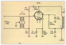
The recent DCPP amplifer monoblock version is using a 4.3K OT. The 6HJ5 tube used has a 280 mA DC current rating. Compare this with a 6L6GC with 110 mA DC current rating. The corresponding OT Zpri for the 6L6GC would then be 280/110 x 4.3K or 11K Ohms !! (Yes, the TV Sweep amplifiers are cheating!)
A thread maybe two years ago did some curve tracer (uTracer) analysis of UL mode at varius % tappings, and was really an eye opener as to what really is going on. Starting from pentode (beam) mode with the typical knees at 0% UL, the knees drop down in current at higher % UL, while the "flat" part of the pentode curves becomes lower Z sloped and flatter. So basically one sees the knee section on the left side sink down with higher %UL, and the "flat" section curvatures gets flatter but steeper.
Going all the way to 100% UL has the knee sections drop to zero current and the "flat" sections develop curvature upwards like triodes. So a flattest curve optimum versus % UL does exist. But the (grid 1, 3/2 power law, really more like square law) gm variation is still in there (spacings).
Taking a little different analysis approach than the usual UL explanation, one can look at ALL the UL tapping cases as triodes with varying Rp. The screen grid DC voltage just pushes the triode curve convergence section off to the left into neg. plate V territory (with the current consumed by the screen grids at 0V causing the usual pentode knee drop-offs.)
Triodes are usually spec'd for loading at 4 to 5 times their Rp to avoid significant gm variation distortion. What the UL mode is doing is to allow us to adjust the tube (hidden triode) Rp down until an optimum Zprimary OT is practical to wind. Hence the optimum UL Zpri is typically a little higher than the pentode OT, but not much. Since the screen grid DC is still keeping the current (and gm) up at the low plate V end (left side) we are still able to enjoy high power output, similar to the pentode case (somewhat higher B+ used in UL typically with the somewhat higher Zpri OT to keep the power up)
Its not real clear whether the straightening of the individual plate curves has much to do with this linearization process. But it looks nice at least. One can look at this all from the pentode perspective too. There, the typical curvature near the knees prevents one from going to a higher Zpri OT (and higher B+) to lower the gm distortion (less current variation giving less gm variation). So returning screen current to the OT taps is helpful there, and incidentally straightening the curves.
Looking at some of the recent TV Sweep tube amps. and comparing their OT Zpri versus cathode current capability to the typical "audio" tube amplifiers ratio, it becomes apparent that they are using much higher OT Zpri/[current rating] than the audio tubes. Almost 2X. As long as screen current distortion does not get in the way, this leads to lower grid 1 gm distortion. Some late TV Sweep tubes have very straight plate curves (from low screen current) and can significantly benefit from using a higher Zpri OT/[current rating]. This all being practically possible since the high Sweep tube current ratings allow low Zpri OTs in the first place. So upping the Zpri/[current rating] just brings them up into the range used by typical "audio" tube designs. You are almost forced to build a better amplifier using TV Sweeps if you use available OTs.
For example:
The recent DCPP amplifer monoblock version is using a 4.3K OT. The 6HJ5 tube used has a 280 mA DC current rating. Compare this with a 6L6GC with 110 mA DC current rating. The corresponding OT Zpri for the 6L6GC would then be 280/110 x 4.3K or 11K Ohms !! (Yes, the TV Sweep amplifiers are cheating!)
Last edited:
It is an example how genius of marketing can write patent papers! 😀
The belief in ultra-linearity of UL still lives, and probably will live forever!
By the way, was an "ultralinear cascode" of 2 FETs already patented?
If not, I claim the priority! 😀
The belief in ultra-linearity of UL still lives, and probably will live forever!
By the way, was an "ultralinear cascode" of 2 FETs already patented?
If not, I claim the priority! 😀
Attachments
![Screenshot-LTspice XVII - [Draft2.asc]-1.png](/community/data/attachments/567/567787-2453ad1548dfbd46b1d6565908b32ac0.jpg?hash=JFOtFUjfvU)
Umm, except the bottom FET is not acting like a triode. So the UL Fdbk above it will not help linearize that. Nice try though.
Could put a triode at the bottom. A Fet cascode up top, with UL Feedback on it's gate.
Being easier to get high current (power) beam pentodes, suggest the improved UltraLinear design below:
All screen current returned to the OT. Screen grid V lowered below the plate V for TV Sweeps. Could make the R1 DC return to a +Vg2 (maybe +60V), instead of the cathode (as shown) for more power capability. R2 could go to a UL tap on the OT also, probably better coupling to the secondary there.
Attachments
Last edited:
Umm, except the bottom FET is not acting like a triode. So the UL Fdbk above it will not help linearize that. Nice try though.
Could put a triode at the bottom. A Fet cascode up top, with UL Feedback on it's gate.
Being easier to get high current (power) beam pentodes, suggest the improved UltraLinear design below:
All screen current returned to the OT. Screen grid V lowered for TV Sweeps. Could make the R1 DC return to a +Vg2, instead of the cathode (as shown) for more power capability.
Use SIT at the bottom! 😀

"Some time ago i proposed an UL mod on a 300B amp on another forum
Mona"
Anatoly, you've been scooped!
Better be nice to Mona now. 😉
Mona"
Anatoly, you've been scooped!
Better be nice to Mona now. 😉
Anatoly, you've been scooped!
Better be nice to Mona now. 😉
I am always nice to him. 🙂
not schade principle at allIt works very well if the right pentode which can run lets say at 50% maximum dissipation. Here is a design worth looking at as that pentode like curve should never change. Think this can be found somewhere at DIY Audio. It is my ideal distortion curve for the pair. Very cunning bias.

i miss the "take exact --% from anode, mix it with input, then feed into grid"
i have been testing Rdivider schade on fets... you must:
* drive it with low impedance
* have adjusted the divider according to Cgd
otherwise gain(mu) / freq is all over the place
this is real schade with transformer drive:
Attachments
Perhaps you could strart a new thread " Schade Amplifiers, not only a semantic problem ? " 😀not schade principle at all
i miss the "take exact --% from anode, mix it with input, then feed into grid"
i have been testing Rdivider schade on fets... you must:
* drive it with low impedance
* have adjusted the divider according to Cgd
otherwise gain(mu) / freq is all over the place
this is real schade with transformer drive:
Mona
Perhaps you could strart a new thread " Schade Amplifiers, not only a semantic problem ? " 😀
Mona
😀
Then some people would chime in and claim that current drive of a resistive feedback divider is equivalent! Then, of course, 2,000 pages later, it will go to The Lounge, switch to cars & boobs. And to Blowtorch Preamp. 😀
hpeter: "this is real schade with transformer drive: ...."
The problem is that real Schade does not have sufficient bandwidth for use as a local loop within global or nested loops. Plus it requires an expensive inter-stage xfmr.
And the "fake" Schade (with resistors) just transfers the linearity problem to the driver instead. Although the RCA 50 Watter version handles that well (added driver cathodes Fdbk).
This all being why I mentioned the N Fdbk to the driver screen grids local Fdbk version (a la Jan Veiset). Or the N Fdbk to the driver cathodes (a la RCA 50 Watter), or the UL local N Fdbk (especially the improved version above, post 188 )
Having cleared all that up,
I should say that real Schade is only suitable in Corvette convertibles with large boobed passengers, in good weather. (no one will notice any deficiencies in the Schade performance) I'm sure we'd all appreciate that tweak/ touch.
Last edited:
Shade advocated a local feedback. Period. Yes, he gave one example, but it was an example only.
You can use higher voltage swing do drive feedback in series, or you can use higher current swing to drive parallel feedback divider. It does not matter. The same cat can be skinned by multiple ways.
Why I use pentode driver and parallel feedback? Because it is easy, and also because it shunts a Miller capacitance.
Like a newspaper man I will attempt the impossible. Write something simple without digging a big hole for myself to fall into. It's worth the risk as so often the basic function of various local feedback types is ignored in favour of which is best. They all have something to offer.
As with newspapers I won't let the truth get in the way of a good story. However I suspect what I say is true. So here goes.
In 1935 Harries Valve Co of London produced a device named a Beam Tetrode. On first look it's a Pentode. Subtly it is not. To the end user it is. Harries sell it to RCA about a year or more later. It returns some years later to the UK under RCA licence as KT66. I show a EL34 as it has more options. Most Pentodes like most Beam Tetrodes have the 3rd grid connected to the cathode inside the device ( EL84 ).
Where I specualte is Power Pentodes and patent busting Bean Tetrodes catch Alan Blumlein's eye in 1935. He is designing cutting lathes so needs every once of power he can get. As cutting uses all sorts of feedback he is very wise to what works. Blumlein has a CAD mind where he can see and rotate ideas like we do in CAD. He sees what to do.
Schade likes his new 807 valve ( new is important as it goes streight into production and use ). However he notices it sounds a bit harsh. He tries simple fake triode connection and regrets the power drop. He experiments with Blumlein's Distributed Load amplifer and find it oscillates. If he were as use to the problems as Blumlein he would have fitted a filter circuit to cure the oscillation. Damn it says Schade it's only shunt feedback and I can do better and not pay patent fees.
Where it is not true is the feedback that UL gives is very nasty in a very helpful way. If it is mixed in the right ratio it is able to get the maximum output for very acceptable distortion type which can look better than triode or pentode on paper. If you look at the curves that is highly debatable.
Surely a pentode with enough feedback is a triode? It's a hard debate. With the Schade feedback we can even reduce the Mu of a fake triode if we want to. Or even a real one like 300B. Goodness knows why we would. With UL we can make one hamonic rise and another fall. That's a neat trick. It's too near to walking on water for my liking ( oscillation ). All the same.
If you look at the Schade example I show the valve or device that comes before as a resistor in red. As a rule the more linear the device is the lower Rp( red ) is. There comes a point when one has defeated the feedback. A typical example is using an ECC82 in place of an ECC81 in the RH34 design of Kitic. What do you see? Very little difference is the answer. The shunt feedback is reduced whilst the ECC82 linearity it is better. This forgets one thing. The application of feedback to the EL34 reduces it's own Rp, Kitic argues lower than a standard fake triode ( I don't know if true, I did notice a drop in gain of about 4 EL34 in or out, less so with ECC82 ). That makes a world of difference when driving a speaker and not using loop feedback.Thus on swings and roundabouts we can win as long as we realise the options for the Rp device are highly limited. Not least if valves are a religion of someone. There are plenty of silicon devices we might use, even bipolar types ( MJE340/350 ? ).
Fake Triode 2 is not to say how to do it. It is to say the other grids can be made to work as a different triode. EL34 allows more grids to be tried. Notice I draw the grid spacings to show they are not really they same. The reason I say Fake Triode is to say the spare grids do slightly change the curves over a true Triode. Looking at the EL 34 graphs they are very like a true triode ( PX25 ? ).
The Quad UL is the one we would struggle to copy. I sort of doubt it is as good as some claim. All the same when analysed it seems to have lower distortion for a certain gain level ( ! ). It is useful to show as it looks more like a pure pentode. The Arrows say the signal is in antiphase.
One thing that has been said that I also doubt is the use of a Pentode/FET in Push Pull Schade Feedback. The use of a pentode with a fake triode is a bit like UL feedback. There is some cuve cancelling that if done with care works almost like UL. Remeber that most gain stages invert so cancellation will happen. Cathode followers often are the wrong solution for this reason alone. Certain if not using measurements don't assume anything just because people say it. As a PP amp has distortion cancellation you might end up with a plate full of pastry and no fruit as your apple pie. My guess is a ECC81 as cathode coupled phase splitter is your better option if building a Schade PP. One can do the Dynaco + 2 x RH34 ( it's mostly the same ).
Shunt feedback is a rather wonderful thing and worth reading up on. Transistors often have better explanations. The gain formula sort of says it deals with transient signals better. That for someone other than a newspaper man to tell.
BTW. I built a cross coupled idea once. It wasn't happy.
BTW. Schade feedback is a pure invention of DIY Audio. Mr Kitic wasn't much liked as he shouted down anyone who would dare discuss his design. Myself, I was rather amused, others were not. So a rather crude name was arrived at which identified Mr Schade as the one to originate it. Mr Harold Black might have something to say if he could be asked.
Thus propper Schade or not propper Schade is all in the imagination of people who never liked Mr Kitic. Lets dump the term and call it what it is. Local shunt feedback. I wrote to Alex recently and begged him to do a PP design if only to show why not. It's my only email of very few to him that received no reply, shame.
Julian Vereker for years had to argue a collector ( anode ) of a NPN device ( like a valve ) with 100 % negative feedback had the same function as a PNP devices emitter. This debate raged for years. It is accepted now he is dead that he was right. Julian also said " NPN and PNP matched devices are as alike as men and women of the same weight and height". Whilst I do not agree totally I think it shows him to have had a lively mind. His NPN device BDY56 was a lot faster in 1974.
I would like to defend Kitic. What he seems to be saying is this neat trick if understood works and is very pure if believing as I do less is better. If changed it is your idea and not his. That seems a fair thing to say.
Last edited:
The local shunt FB, when done with a triode, as Mr. Kitic did in his RH amps leaves a variable resistor in the FB path( the triode's plate ). The E-Linear amp done by Pete Millett for AudioXpress uses a pentode, and that amp can( and has been ) folded over/duplicated for PP topology.( well, IMO that 'duplicated' is not quite accurate, as those of us who coined the term E-Linear were dealing with only PP at the time, and we beat Mr. Millett by at least a few weeks in developing the circuit )
A LTP of pentodes does a very fine job, even 6AU6's with their generous g2 currents. EL84 works quite well, as does a cascode( triode on the bottom, MOSFET on top ). I have two very nice PP Class A amps running now, one with EL84 and one with a 6H6 under a pair of FQP1N60 Fairchild transistors. 6CL6 and 6V6 also do quite well...LOL
cheers,
Douglas
- Status
- Not open for further replies.
- Home
- Amplifiers
- Tubes / Valves
- Schade Feedback In A Push Pull Differential Amplifier?