Not exactly "technical" interpretations, and using a JFET/tube cascode instead of a pentode driver But he said it was possible to balance the two loops for best results. Is the RCA design balanced by these criteria somehow?
I do not know, but in my designs loops are balanced, to get an optimal results from tubes that I selected to use.
First of all, I am getting low intermods at medium power and still smooth clipping, then I just check frequency response, and if transformers are good, it is more than adequate. Like from 4Hz to 120 KHz from 5W/Ch amp with simple Edcor transformers, with no need for additional compensation.
All that synaesthesia is hard to use since I am well trained to hear and identify distortions.
Yes indeed, these days I would well imagine tweaking each N Fdbk loop for best overall results (FFT analyzer).
But the RCA 50 Watt design seems to have chosen somewhat incompatible N Fdbk loops. But I do imagine that local (typically nested) loops may leave a residual distortion with some slight curvature. And a loop from a 180 degree inverted stage likely leaves the opposite slight curvature residual as the one from the 0 degree stage, so some type of residual nulling might be possible. Maybe this is what is going on in balancing one against the other.
The interesting detail is that the RCA 50 W design takes from the same Fdbk point and goes back to 180 degree inverted insertion points. (6CB6 cathode or plate) While the Citation II takes from two different (180 delta) points and inserts them both back at the same point (driver grids). Something of a subtle symmetry there.
Might be interesting to combine both styles with 4 N Fdbk loops. 😱
Will at least win the award for the most complicated amplifier anyway. 😎
Last edited:
The interesting detail is that the RCA 50 W design takes from the same Fdbk point and goes back to 180 degree inverted insertion points.
Think again. ;-)
OH, yes, quite right.
Both do end up as N Fdbk loops. What I meant was that there is a gain stage in between them (6CB6). Normally thought of as an inverting stage, but not so for cathode and plate. In which case both would seem to produce the same type of residual curvature. ----OK--- theory shot down. 🙄
Wait a minute. The 2nd harmonic distortion of the 6CB6 is bending the cathode correction one way, while the 2nd harmonic dist. of the outputs is bending that correction the other way. The Yin-Yang Residual Bending Theory still working I think.
Each N Fdbk loop type leaves some slight residual bend in the transfer function. (for finite loop gain) And the two loop types leave opposite type bends, which could be balanced out somewhat.
Maybe another way to look at it would be that the inner loop corrects the curvature of the output stage sufficiently to match the opposite curvature of the driver stage, hopefully near nulling each other. Then the outer loop reduces what little is left to insignificance.
Looking at it in this last fashion then leads me to think that the Citation II is doing it all wrong then. The inner loop there reduces the driver distortion to insignificance, so nothing is left to cancel with the output stage dist. 😕
Last edited:
Upper loop corrects errors of output stage, middle loop corrects errors of this correction, the global loop corrects the rest. 🙂
To avoid shock think of what happen in each stage when the amp misbehaves, i.e. on extremes. When it behaves, it is nothing special, except frequency response.
Oh, I forgot the Citation II also has UL Fdbks for the output stage. So 3 "local" loops + global. Maybe the UL loop is sufficient to get the output stage distortion comparable to the driver dist. The little loop around the driver stage is still not making a whole lot of sense though, especially when both N Fdbks go to the same driver grids and partially conflict.
I think the "Schade" like N Fdbks (plate to plate) of the RCA 50 Watter need fixing.
Instead of going back to the 6CB6 plates, they should go (crossed) to the 6CB6 screen grids. That way the loop gain for the cathode N Fdbk loops is left intact and powerful. Probably leaving such low residual distortion then that it will be called "flat" 🙄 And hard clipping too. Can't win.
Wait, wait.. On the original RCA 50 W, when the output tube saturates, it has very low impedance at the plates, which kills the loop gain for the driver tube. Preventing hard clipping. Maybe. Ie, the driver loop gain goes down as the output tube nears saturation. Tough way to do it though.
Last edited:
When we compare triode pentode, it looks like the pentode performs better.The input votage for the triode is much more assymetric.
Not impossible someone is trying matching that to the same kind of (inverted)distortion in the power tubes.
Mona
It works very well if the right pentode which can run lets say at 50% maximum dissipation. Here is a design worth looking at as that pentode like curve should never change. Think this can be found somewhere at DIY Audio. It is my ideal distortion curve for the pair. Very cunning bias.

That's the tip of the iceburg. What I really dislike about PP is the way nice harmonics get cancelled. Thus a lot of what you see is thrown away. I guess that's saying SE is better. I mostly came to that belief. For more power the old Hitachi MOSFET design is very close to a valve sound. I hate saying it that way except it is true. Their distortion is very low which proves high negative feedback and good open sound is possible.
"For more power the old Hitachi MOSFET design is very close to a valve sound."
Schematic? Model? Class of operation?
Not too surprising, considering that tube grid 1 response is mostly square law and Mosfets are too. Control of gate Cap. would be key. Square law in P-P mode with class A operation gives constant net gm, Shangri-La.
However, we have Crazy/Twin drive now, for constant gm in near class B, P-P, --without-- all the heat.
Last edited:
HH-1200 and old Maplin kit LP56 were typical. The Maplin kit even had the very top spec Japanese devices like 2SC716 and 2SD756 which were much better than the MPSA42/92 of HH. Even so the HH was a very OK version. The HH also proves most of the nonsense talked about this type of FET is simply not true. Cgs is bootstrapped to the load so is not the factor it is thought to be. Cgd is. The JLH amplifier is the most interesting of all ( circa 1980 ). The Cgs is important when this design, however he side steps the problem. Also he shows the stability of a complimentary bipolar-FET feedback pair is no problem at all! JLH returned to capacitor coupling as he found he liked it better, his 1975 design was DC coupled. JLH is someone I never met who would have been my hero. An antimater Douglas Self.
BTW. Devices like Exicon 10N/P20 need very low bias voltages compared with the anti FET folklaw. Less than a Darlington and not very different to a complimentary bipolar feedback pair and no chance of thermal runaway if a sensible heatsink used. The Hitachi double long tail pair ( LTP ) is a nice touch. Current mirror to LTP2 and double constant voltage clamping to LTP1, good slewing that is symetrical and only 7 devices. It has a small tweak to avoid the very hostile ideas of others about double VAS designs. The distortion at 100 kHz is very low as a result. Power bandwidth is fully that. It puts a typical Hypex to shame.
BTW. Devices like Exicon 10N/P20 need very low bias voltages compared with the anti FET folklaw. Less than a Darlington and not very different to a complimentary bipolar feedback pair and no chance of thermal runaway if a sensible heatsink used. The Hitachi double long tail pair ( LTP ) is a nice touch. Current mirror to LTP2 and double constant voltage clamping to LTP1, good slewing that is symetrical and only 7 devices. It has a small tweak to avoid the very hostile ideas of others about double VAS designs. The distortion at 100 kHz is very low as a result. Power bandwidth is fully that. It puts a typical Hypex to shame.
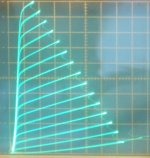
Space age constant gm tubes (most any TV Sweep tube eligible):
Attachments
Last edited:

As far as I know this is the actual Hitachi version and is the one that most people doubt as being possible ( Page 5 of application notes ). Notice the power bandwidth is not bad, what tweeter really needs > 100 watts ? It wouldn't mind 4 ohms either. The sub 2 watts is very good if 100 mA per pair standing current used. The single version from Maplin gave 90 watts at +/-56 VDC and 150 watts 4R. As the Hitachi used a higher voltage it's output would be higher.
The somewhat similar 1982 JLH 100 W Mosfet amplifier:
http://www.keith-snook.info/wireles...d-1982/80-100 Watt Mosfet Audio Amplifier.pdf
Both high gain, high N Fdbk, with lateral Mosfet outputs as followers, no nested Fdbk loops (except Miller comp). High bias current for crossover. Pretty much the basic SS paradigm Mosfet amplifier design before all the glamorous super-symmetric dual VAS designs came out.
------------------------------------------------
Changing the RCA 50 W amplifier to "local" driver screen grid Fdbks (crossed), instead of the P to P "Schade" like loops, would give pretty much the same results. (very high gain in the "local" driver cathodes N-Fdbk loops). Using Jan Veiset's proportional screen V to plate V driver N-Fdbk rules would keep the dual pentode driver stage acting like high gain triodes (the screen N-Fdbk inputs are kept constant Z by constant fraction of driver plate current intercepted there, via proportional voltages). Optional gyrator loads on the driver plates for extreme loop gain. Elegant, powerful. Way beyond Citation II or Mac. Could upgrade to Crazy/Twin drive TV Sweep outputs (near class B, low Z OT), for linear, high BW, stages from input to output. Would be the first such truly linear amplifier ever designed.
Last edited:
There are 2 ardavtages,
1. 2 LTP stages for better CMRR,
2. No birth defect of voltage biased output emitter followers.
I run my woofers in HT by Haffler amp, it is nice!
1. 2 LTP stages for better CMRR,
2. No birth defect of voltage biased output emitter followers.
I run my woofers in HT by Haffler amp, it is nice!
I fancy Mr Schade designed the circa 1960 RCA amp. His finger prints are all over it. Now the 7199 isn't in production people use the TV type instead. Correction, Sovtek have a 7199. 6U8A,6AN8A and ECF80 seem TV types that could work. If I am right 6U8A is a very small Beam Tetrode doing the work of a Pentode. The story goes that RCA spent money to improve the TV types to make them true low hum, it is said they have extra shielding and less microphonic. RCA like Mullard had many circuits offered as generic designs to push the product. I always thought it odd Dynaco got the credit for the ST70 when it seems a standard RCA idea. However like engines it's the detailing that matters and the output transformer could be make or brake it. Also that it was a kit makes it very different. Personally I was always more impressed with it's simplicity more than it's sound. It seems way behind a Marantz 9. However that might be like saying a Mazda MX5 is way behind a Mercades of the higher order. The RCA/Dynaco is an unusual example of negative feedback which can work. All the real work is done by the pentode of the 7199. From memory it has more than double the gain of EF86. The output is DC coupled to the concertina phase splitter that has no voltage gain ( has a difference of 2 ). Next AC coupled to two EL34 in fixed bias ( brave ). Then the Hafler UL trade mark use of the EL34 ( G2 voltage seems high). Linearity comes from loop negative feedback and some pentode degeneration. Remarkable distortion considering the pentode has all the work to do. If one takes the transformer into picture the EL 34's have a gain of less than unity. I could imagine the Dynaco could work better with 50% of it's feedback being Schade. It still might give enough damping for most speakers. I would exspect the mildly nasel sound to become more open. The problem would be the phase splitter. Pehaps the better way would be shunt feedback around the input pentode and relax the loop feedback. It's the best I can see working. The overal distortion should be similar with slightly more bass bloom/boom. The midband sound slightly more open. If the input was made fake triode I doubt it would have enough gain.
To give the Hitachi plug. I had on loan an Art Audio 300B amp with experimental dull emission 300B by Kron. The sound was what I have never heard from 300B since. Ricardo told me just before he died that he couldn't give them away. The test set up Garrard 501 and ESL57 and a really nice Art preamp. The old Decca World of Stereophonic Sound record ( Both valve and transistor cut, I prefer the transistor cut on light blue Decca as I feel is shows the dynamics better). A train enters a station and people get out and then a beautiful steam whistle. Both amplifiers sound very alike except the Hitachi shows the roof of the station and it's echo's. All the music tacks show similarity. Although the designer of Art was unimpressed ( ? ) we did talk about me getting some 211 to work. It never happened and it would have been fun. I think the amp was one intended for Tom Fletcher which Tom never got to hear. I suspect I would have used FET input in my home version. No FET DC coupling for me. I am not that brave. It was running 800V. I planned to use 1000. 813 is looks interesting. Art has a pile of 211 he bought years ago and never used.
If you look at Radford STA15/2 it has a valve much like 7199 in a very strange long tail pair . Some said it was easier to drive as an input pentode. I doubt that. I think it gave lower and nicer distortion. My name for this is East West UL ( N S is standard UL ). Having never tried the actual curves it is a guess. In my version one inverts the stage ( pentode anode to triode voltage amp grid ). Radford were not people to do something like this without a very cunning reason. It looks a complete no-no if a DIY Audio newby sent it in.
Circuit Diagrams of Radford MA/STA amplifiers
http://www.quadesl.com/schematics/quad2.gif
I wonder if the Quad ii is a good place to start a Schade feedback PP amp. The EF86 proves it can just about drive a KT66. The 86 being the prefered pentode type over ECC81 often used. As far as I can see only the long tail pair ( LTP ) can offer the ideal simplicity we need as the phase splitter here ( not Dynaco ). The tail could be made longer than typical designs were with extra -ve rail.
ECC81 is able to work as a LTP phase splitter of higher Rp than most triodes, see link. It also can offer current. This gives ways of converting a RH34 or whatever to PP. Where it goes is not an easy guess. The valve before the LTP could tune the circuit. RH34 is not very sensetive so a pre LTP valve would be needed. I would strongly recomend UL feedback if your transformer allows it. I would avoid loop feedback if you can. UL + Loop is tricky, I wrongly blamed UL for that in the past. Loop feedback to the ECC81 tails if needs must.
I have used 82% triode UL as it was a quirk of my transformer. Although UL graphs show no advantage to it I found where a triode was required it was like a usefully higher gain triode, my spectrums looked identical. My SE driven PP out amp favoured all triode devices and does have the second harmonic higher than the third which I prefer. Having a 82% triode UL would be ideal for it. That circuit was a high power output LTP that works very well even with totally mismatched valves. That was my big doubt. That circuit was my fake 211 driver. The LTP 2 x EL34 being the fake 211.
The Valve Wizard -Long Tail Pair
This looks workable for a Schade PP. The EF86 could be something else. ECC81 anode resistors need thought. EF184 ( I hope that's the number ) were the pentode that was very like an ECC81 if triode connected. That would be very interesting if used as a LTP pentode phase splitter. One could use LTP ECC82 cascodes. I doubt it any better than ECC81 from my measurements and needs more devices.
The Valve Wizard
Last edited:
In your scheme, feedback is applied only to the top cathode, as the bottom cathode is grounded. For cathode feedback you need a secondary winding with a center tap, which goes to ground. 16 Ohm speaker winding with 4 Ohm tap might do the trick, but the depth of feedback will be insufficient to have any benefit. You need to apply 20-30% of plate-to-plate swing to cathodes to have a meaningful effect, which means OPT with special feedback winding. This was done in a number of commercial designs.
...but also the 0-4-16 ohms trick shown by Wavebourn. E.g. see the Leslie 147 amp schematics. Btw, this one also features Schade feedback.
Best regards!
Here is Jan Veiset's 2007 complex driver scheme:
Feedback scheme.
I think he didn't get this working due to instability problems, last I heard. (CFB phase issue?)
The two interesting points are the driver stage with crossed g2 feedbacks, and CFB from the secondary back to the driver stage cathodes.
Adapting this to the RCA 50 Watter:
Remove the "Schade" like P to P Fdbks. Use the crossed g2 Fdbks instead. Fdbk attenuators are designed so that the driver plates and g2's are kept in voltage proportion. That keeps the % distribution of screen current to plate current constant. (so the g2 loading impedance stays constant, otherwise Mosfet followers needed for the screen drives) Using this local N-Fdbk, instead of the "Schade" Fdbks, keeps the loop gain high for the driver, but the driver behaves like a low Mu triode for overall gain control (Fdbk-wise). (but still has high loop gain from the pentode outputs)
The driver stage cathodes could still operate as in the RCA design, or could use the secondary winding as CFB (like in Veiset's schematic) -if- it can be made stable. The secondary has phase shift from loading across the OT leakage L, and the gain is high at the driver cathodes. (much safer to stick with the original RCA approach here, using the primary side, or UL taps)
Attachments
- Status
- Not open for further replies.
- Home
- Amplifiers
- Tubes / Valves
- Schade Feedback In A Push Pull Differential Amplifier?