Hey Guys,
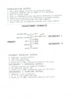
I contacted my winder with the requirements for the output transformers I want. He quoted me $260 for the pair. And then told me he had these, (see attached) on the shelf and I could have them for $100 the pair! Some days you get the bear!
The tertiary secondary winding is 16 ohms. I plan to use that for the cathode applied feedback for KT77. I asked for a little more P-P And I was going to add a second UL type tap on the primary at 10%. But for that price and immediate shipping I'm dancing a jig!
And another question? Has anyone ever applied feedback to G1 of the output tube? I've never seen it. But it seems like the most logical place to apply feedback, right at the input.
Attachments
The Schade feedback is more or less g1 feedback. The feedback isn't to an anode really. The high impedance of the anode allows the two dvice to unite. One still has to finely judge the anode resistance ( 100 K ? ) to get the best compromise. It needs to be as high as possible without clipping as the most obvious problem.
Looking at it another way. The Rp if I am not mistaken for 6550A is about 32K ohms pure tetrode ( pentode ), yikes that's high. If g2 triode about 1K ohms. It is easy to see how that will improve the ability of the valve to cope with the speaker. Taking the anode to anode of the transformer at a possible 5 K we can see the sums look very reasonable. If UL connect the anode I suspect is about 2K3 per device. Now one can see how that might work. Kitic claimed something of the order of 900R for his version. Looking at it a different way. If UL and a 4 ohms tap feeding an 8 ohms speaker it might be best of all worlds. Sometimes not true as the 8 ohms tap is better in terms of winding than 4 ohms. One might find this the better triode. If the speaker is a nicer than average load the UL might be total winner as it sould be about twice the sensetivity.
One idea you can look at is to drive a speaker bewteen 100 Hz and whatever with this amplifier. This should overcome any damping factor problems and that of nasty port loading ( convert to resistive port using drinking strews perhaps ). My subwoffer is an open baffle with 15 inch driver. It is good for 30 Hz - 12 dB and 40 Hz flat ( measuered ). It needs minimum 100 watts to work yet is seldom fully used by real music. To set the amplifer this way only needs the input capacitor reduced in size for 100 Hz limit. If 470 K ( input to ground ) it would be in the 3.3 nF region. That's cheap and nice quality. I dare say 10 nF would be best. Why buy exspesive caps that might suit worse.
I was trying to find an ECF82 in my tin of valves. Alas no, I would love to plot how the phase splitter works. My goodness I will have to buy two. I have a hunch it will be far better than even I think. I will do it the Bailey way and the primitive way. No one seems to be able to say if a mini beam tetrode. I found some DF96 which I didn't know I had!
And another question? Has anyone ever applied feedback to G1 of the output tube? I've never seen it. But it seems like the most logical place to apply feedback, right at the input.
Sure, I have. See here for an example of doing it in an output stage. The problem you get is that parallel applied feedback to the grid lowers input impedance of the stage so I drove it with a p-channel mosfet follower. I chose p-channel because that made it so that I could direct-couple to the feedback divider *and* drive it from a low impedance.
I have also taken the same approach with a ccs-loaded pentode (yes, you read that right) and I have achieved absurdly low distortion at ridiculously large output voltage swings. The crazy thing is, I can achieve *much* lower levels of high-order harmonics with an EL84 or EL34 than I can with DHTs or IDHTs. I think I will stick with pentodes whenever I need large swings at low distortion. It is just by far the best approach that I have ever seen. See here for the circuit and measurements.
Now, as Nigel said above, the plate-to-plate feedback configuration is also plate-to-grid feedback since the plate of the driver and the grid of the output tube are connected. This makes the driver a current-to-voltage converter so you want a driver with a very linear voltage to current characteristics. In other words, you want pentode-like characteristics with even spacing when working into a very steep load line. The curves of a pentode working into a vertical load line are not nearly as linear as the curves of a triode working into a horizontal load line (which is what I use to drive my circuit, a CCS-loaded triode), which is I think why I get such good results with my approach. Degeneration on the pentode can help linearize the curve spacing, but it still isn't perfect. Basically, I have found that a low-impedance source (a fet follower) driving a resistor is a more linear current-to-voltage converter than a pentode.
It is very frustrating to work out these options. Perhaps I should swallow my pride and build my op amp gain stage with EL 84 triode driving EL 34 or 6550A. Then have UL and triode options. It looks too good to reject.
My existing SE amp ( not shown ) has the simplicity I seek. However in the quest to make it more universal I might add cathode feedback. I will do this for two reasons. Drive a modern speaker better. And also reduce DC in the transformer core. I have about 5% THD mostly second harmonic at 16 Hz. I fancy this would hold off to 10 Hz. The 25 Hz results is 1%. I would again use an op amp. In one thread a guy was told the best tube he could buy was a paper clip. I liked that. Design the amp so removing a valve removes add ons. Anyone know where to buy 9 pin valve plugs ? I fancy showing a friend how his amp could sound without loop feedback. We just remove the ECC83.
One guy talking of cathode feedback said a 6550A needs 61 Vrms. That implies more than 120 V rms to do my SE PP idea, That's bonkers. Cathode feedback can be done by cross coupling the UL taps via capacitors. That is not very practical. What it does show is UL is a very curious feedback. It feels more like bootsrapping to me except it has different outcomes. The simplest thing you can say is it doubles the gain for double the Rp roughly speaking. By using the 4 ohm tap and no loop feedback I suspect it should sound better on all counts. That is it does exactly the same as it would at 8R triode except it is more linear. Not a free lunch, just a better chef.
The Kitic design almost feels like class A2 in how it draws down the gain.
Hey Guys,
I contacted my winder with the requirements for the output transformers I want. He quoted me $260 for the pair. And then told me he had these, (see attached) on the shelf and I could have them for $100 the pair! Some days you get the bear!
How does "600 volt insulation rating" translate to the amount of voltage that can actually be applied to the primary? That seems low. Otherwise, they sound like a steal.
Win W5JAG
Win, you are correct; the primary insulation should be in the range of 1500 to 2000 volts...transients can puncture insulation! Hang a scope on the primary of a EL34-type output transformer and look at the transients when driving the amp with complex input or square wave. The feed back loops in the RCA 50 w amplifier can be "tuned" for best square wave response through the amplifier. I never liked the 7199. The 6GH8 is a better choice. Best choice is all triode driver, directly coupled to the output tube grids off the cathodes of the push pull driver. (The bias for the output grids is set by the IR drop across each driver cathode resistor.) Interstage coupling using a transformer or coupling capacitors may reduce the risk of "red plating" a output tube, but careful driver stage design can greatly reduce risks.It is very frustrating to work out these options. Perhaps I should swallow my pride and build my op amp gain stage with EL 84 triode driving EL 34 or 6550A. Then have UL and triode options. It looks too good to reject.
My existing SE amp ( not shown ) has the simplicity I seek. However in the quest to make it more universal I might add cathode feedback. I will do this for two reasons. Drive a modern speaker better. And also reduce DC in the transformer core. I have about 5% THD mostly second harmonic at 16 Hz. I fancy this would hold off to 10 Hz. The 25 Hz results is 1%. I would again use an op amp. In one thread a guy was told the best tube he could buy was a paper clip. I liked that. Design the amp so removing a valve removes add ons. Anyone know where to buy 9 pin valve plugs ? I fancy showing a friend how his amp could sound without loop feedback. We just remove the ECC83.
One guy talking of cathode feedback said a 6550A needs 61 Vrms. That implies more than 120 V rms to do my SE PP idea, That's bonkers. Cathode feedback can be done by cross coupling the UL taps via capacitors. That is not very practical. What it does show is UL is a very curious feedback. It feels more like bootsrapping to me except it has different outcomes. The simplest thing you can say is it doubles the gain for double the Rp roughly speaking. By using the 4 ohm tap and no loop feedback I suspect it should sound better on all counts. That is it does exactly the same as it would at 8R triode except it is more linear. Not a free lunch, just a better chef.
The Kitic design almost feels like class A2 in how it draws down the gain.
For test purposes, the amp must be terminated in a speaker load, a resistor, or other suitable load.
I did some soul searching with this. Having only heard low quality valve amplifers when young I thought hum, hiss, and colouration were what valves did. It was a shock to find a valve amp could be free of these problems. The next shock was to find some aspects of sound were more real, equally some transistor amps sounded more real in other equally important ways. Gradually I started to hear problems with valve amplifiers. Then I heard better SE valve amps and thought that they solved these problems. Making my own made me even more certain. Trends in now SE amps I think bring back what I dislike.
In my post 104 I think that's about the best I will do. My final version didn't have the current source and sink. UL would be a good option.
A transformer with UL to the EL 84 driver could be an idea. As I can have many mA's to play with these can be exchanged for voltage swing. It could be centre tapped output to do PP drive with identical drive ability ( same transformer ). The risk there is a distortion spectrum that is unlikely to please me.
Here is something I understood a long time ago which still seems to escape valve fanatics. In the 1950's when the Quad ESL arrived serrious attempts were made to understand hearing. It was stated this way. If the 1/3 harmonic was less than 0.3% and the harmonics fell on an exponetial curve with no harmonic higher or lower than it should be, that was perfect. One can not remove the higher 2 nd harmonic and infer that's better as many do.The analogy is good lighting that is so natural it seems there is none. That analogy holds up in that it is perhaps better than real life. It isn't obvious until someone switches that light off. In a lessor amplifier if the fifth harmonic was below 0.1% that would be good. This was lumped together to say 0.1% THD would be hi fi. That last bit was probably wrong. Halogen lighting if you like. Not bad, but.
The Quad 303 has exactly the right distortion on all counts and is a very nice sounding amplifer. It has a certain sound even though at 0.01% 1/3 rd or better. Even with this perfect spectrum many try to remove it's 2 nd harmonic which is easy to do. Crazy.
My friend Sid Smith said " Nigel, you really must try listening to capacitors. I didn't believe it until I repaired an amplifer and Ijaz insisted I fitted them". Ijaz a mutual friend. Sid went on to say his transistor designs might be highly regarded if the same trouble taken ( Ditto Quad ). The Marantz Model 9 is perhaps the better amplifier I ever heard. Sid used Quad ESL 63 bare. Taking the covers off makes a big difference. 63's are not the poor relation then. As far as I know Quad's need no damping factor. My SE amps sound wonderful via 63's. The bass sounds very like real music.
What I see in treads is valve designs that don't accept that in some way transistors win the numbers games. The game valves can win is how few devices to get 1% THD that falls to lets say 0.% % 1 watt. The spud amp contest takes it too far. My friends paid for me to do that. I refused as it was a waste of my time.
I was in a car with Sid going into NY. He said " Look at the Twin Towers " I pointed to the Chrysler Building as my favourite. I then said " Sid , you know in every good triode there is a better pentode trying to get out ". Sid nearly crashed the car. Myself, Sid, Ijaz and Terry of Garrard went to a dinner on Long Island. Sid drew me load lines etc. I then told it from the point of view of being a transistion resistance device. Sid smiled and said " Nigel, my favourite Triode is a Pentode. Maybe you don't talk nonsense after all ". It was EL 34. Sid died soon afterwards, no one realised he was ill. So many questions I never asked.
Sid showed me how a LM317 could be made to deal with ripple in a PSU at 450 VDC. I found a capacitance multiplier using FET could equal it without so much circuitry.
My point right or wrong is the distortion type, absolute level and power I show in 104 seems right to me. As I would like to complete that amp an op amp will have to do the duty. MC33078 is cheap and nice. OP2604 also.
One point. Some DC in the PP transformer may be a good thing. It woud be remarkable if SE cathode feedback could do it by happy accident ( looks possible ) . The conjecture is the windings are never perfect which saves the day. A certain level of DC will not change things too much. What is might do is move the iron into a more linear region ( BH curve ) for no obvious loss. This could be mistaken for what the cathode feedback does. If true the trait of an SE amp might be heard. That is micro detail at very low levels. I can get 7 Vrms from an op amp ( more ), the load into an EL 84 is ideal ( class A without asking, SE class A if I prefer using a pull down resitor to - ve rail ). I could have some cathode feedback inside my concept amp. People really seem to like cathode with UL. I can see why. It gives you a slightly better triode. Gain should be identical. If I am not wrong damping factor could be slightly better. 4 would suit me fine. There are other reason why valves have better micro detail. I have no interest in saying why ( OPA2604 also, it's not JFET square laws ) . The main thing is make sure you hear it.
Nigel, DC in any push-pull transformer will definitely lower its inductance, perhaps rather sharply.
SpreadSpectrum, I must say how elegant your way of applying the plate to grid feedback is. I'm definitely going to try this with high gm sweep tubes. One thing that puzzled me; why such a high negative voltage to the drain of the p mosfet?
SpreadSpectrum, I must say how elegant your way of applying the plate to grid feedback is. I'm definitely going to try this with high gm sweep tubes. One thing that puzzled me; why such a high negative voltage to the drain of the p mosfet?

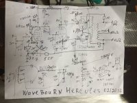
Here is my " perfect " concept amp. I haven't found a transformer that gives me this. Danbury can do 1:2 which seems too little. I suspect choke loading to the EL 84 would be a free lunch. UL is option on driver and outputs. No idea of how best to do the transformer to EL 34 g1 so just concept. I would like 0.6 V rms in = 12 watts triode. This is the advantage of EL 84 over ECC82 etc. It can offer more current. ECC82 I guess at a pinch can swing 50 V rms.
The 1 watt graph is to remind me where I started. When people say valve amps have all second harmonic they mean this. The 3 rd is off the scope. Give it some gain and often it is exactly where it should be.
Nigel, DC in any push-pull transformer will definitely lower its inductance, perhaps rather sharply.
SpreadSpectrum, I must say how elegant your way of applying the plate to grid feedback is. I'm definitely going to try this with high gm sweep tubes. One thing that puzzled me; why such a high negative voltage to the drain of the p mosfet?
I suppose that must be right. When SE amp it should be beter as in DC antiphase. AC bias is an idea, 80 kHz ?
SpreadSpectrum, I must say how elegant your way of applying the plate to grid feedback is. I'm definitely going to try this with high gm sweep tubes. One thing that puzzled me; why such a high negative voltage to the drain of the p mosfet?
I built that amp to experiment with various feedback ratios. The more feedback you use, the more negatively you have to bias the fet and the more negative swing you need. I finally settled on 20% of plate signal fed back. It is pretty much the same feedback circuit as an inverting op-amp, but the pfet makes it all link up nicely with no caps.
So the answer is that the amp is over-built for the amount of feedback used. The negative rail can be lowered. It only has to handle the negative bias plus swing plus a little headroom to keep Crss of the fet in a linear region. It should be easy to work out for any particular situation.
I'm an amateur and as such have a very limited knowledge of SS transistors and their application to tube circuits. So I'll stick to what I almost know.
I've been reading about feedback and transformers. The amp I'm working on at the moment is a differential amp with an input transformer driving a pair of 6N6P triodes into an interstage transformer which drives a pair of 6L6's into an Eico ST70 output transformer. I would like to keep the feedback to a minimum and also local. My research into feedback shows me that feedback can be applied almost anywhere in a circuit when approximately 180 degrees out of phase.
So please tell me If this plan is incorrect? Since the secondary output of the output transformers is 180 degrees out of phase with the primary and the plates it seems logical to apply the feedback from the secondary of the OT to either the plate or the cathode of the output tubes. Assuming I can identify the transformer leads correctly I can connect the end taps of the secondary to either the cathode or the plate of the 6L6's. And since the transformer secondary is low voltage AC and high current the feedback can be moderated with a simple resistor.
The problem is it seldom is 180 degrees, worse still when most important the problem begins. UL and triode are both feedack types. If you use a 4 ohm tap to drive 8ohms you mimic one quality of feedback. The load the valve sees is nicer. 6550A is approximately 2K3 typical UL and 1K1 triode. If the transfomer is 5 K anode to anode the UL shows near equlaity. Cathode feedback might be 770R. However it comes with almost impossible drive requirements when wanting a simple idea. Far better to use triode with 4 ohm tap if it has the similar grip of the speaker. This can be mistaken for lower distortion. The 8 ohm tap is at hand if wanting it slightly louder.
Reading this link won't help make it easy. All the same most questions are answered. I hadn't considered my test bed PP as having current feedback ( CCSink ). It does and that isn't the most helpful thing in what I wanted. I don't want to exagerate the 180 degrees thing except to say when loop feedback the amplifer can oscillate if phase shift is enough. Usually the feedback has to be reduced at some point to stop this. With local feedback the problem should be reduced. UL always looks a bit suspect from this point of view.
One thing I didn't research enough was Kitic's assertion that ECC 82 wouldn't work. Mostly I agree in terms of what I thought I saw. However it's Rp isn't so low as to make it impossible. It might be enough to please.
Audio amplifier push pull output stage.
One thing I didn't research enough was Kitic's assertion that ECC 82 wouldn't work. Mostly I agree in terms of what I thought I saw. However it's Rp isn't so low as to make it impossible. It might be enough to please.
Audio amplifier push pull output stage.
http://www.diyaudio.com/forums/tubes-valves/73508-cascoded-long-tail-pair-inferno.html#post869932
Although he didn't seem to arrive at a good solution this mixed with the Baby Huey ideas could work. I think there was a Huey with larger outputs. The idea of a Cascode Long Tail Pair ( See Morgan Jones on Cascodes and Keith Snook Quad 2/22 ) could work. I suspect ECC88 would be prefered. This would combine good gain with very high Rp to help Schade feedback. I would love to see if that has been done. I suspect ECC82 wouldn't be so bad used this way. As with the Huey well judged UL feedback is an option ( grid stoppers to UL taps for example ). The cascode is a better pentode in many ways. Mostly as we have more choices.
http://www.keith-snook.info/wireles...A.F. Amplifier - Long-tailed cascode pair.pdf
Schade feedback question
I was wondering if I could get rid of my global feedback and apply schade feedback to my dynaco st70. Output tubes are currently 6p3se russian. What would be involved and could it be applied? Here a pic of the schematic:
I was wondering if I could get rid of my global feedback and apply schade feedback to my dynaco st70. Output tubes are currently 6p3se russian. What would be involved and could it be applied? Here a pic of the schematic:
An externally hosted image should be here but it was not working when we last tested it.
What's the point of getting rid of global feedback?
You can add local feedback around output tubes. It will decrease global feedback.
Here is my example:
the same phase splitter like yours, so you can't add parallel feedback from anodes. But you can add feedback in series to cathodes. Your transformer also has 4 and 16 Ohm secondaries, like mine does.
Shade, strictly speaking, just suggested local feedback added around output tubes. And his example included phase-splitting transformer.
Attachments
Anything I missed? Kinda new to this.
An externally hosted image should be here but it was not working when we last tested it.
In your scheme, feedback is applied only to the top cathode, as the bottom cathode is grounded. For cathode feedback you need a secondary winding with a center tap, which goes to ground. 16 Ohm speaker winding with 4 Ohm tap might do the trick, but the depth of feedback will be insufficient to have any benefit. You need to apply 20-30% of plate-to-plate swing to cathodes to have a meaningful effect, which means OPT with special feedback winding. This was done in a number of commercial designs.
- Status
- Not open for further replies.
- Home
- Amplifiers
- Tubes / Valves
- Schade Feedback In A Push Pull Differential Amplifier?