I found it best to start is with a known design. The Dynaco is a good place to start. Next I would suggest buying a spectrum analyser and make a low distortion sine wave oscillator. Here is one adapted from the Analogue Cookbook ( about 1990 ). R5 33K sets the output. If you need a slight tweek it is OK to adjust this. If wanting more give the last op amp some gain. Two very cheap PP3 9V ransistor radio batteries will serve well as the ideal power supply. The R6C1 R8C2 values I give are as close as you will get with standard spec components. I have found 10% mylar capacitors to give very good results and are very cheap, GOG NPO ceramics are slightly better. Mostly for audio work " in the region of " is more than useful. The 47K in paralell with the 2x 1N4148 is to slightly reduce distortion, lower will stall the oscillation. The 27K ( HP ) 3K ( LP ) gives the best distortion compromise. Typically 0.05% or better. The 27K + 3K gives a 1/9 ratio for 3rd harmonic reduction. From memory distortion improves from -52 dB to -66 dB. The 5th harmonic is slightly worse due to this nulling, however still about -66 dB. The build is very simple on 1 x 2 " stripboard. Use op amp 1 ( left top )as R6 C1 and op amp 4 ( right top )as R8 C2 for the easiest layout. Notice some op amps + inputs are taken to 0V, this can be handy for layout ( eg 1N4148 ). 10 nF + to - ( pins 4 and 11 ) on the TL074 is useful to ensure stability.
From memory the output should suit a Dynaco. If more wanted higher output and greater temperature stability swap 2 x 1N4148 for RED LED's ( note one is upside down ). R5 R7 and the paralell resistor could be 22K. Output might be 5V rms which is on the limit of a new set of PP3 zinc batteries. All from memory so you will have to test it for yourself if LED's. The near 7V rms I show was with R5 set to 33K if I remember using a 15VDC +/- supply. Note the distortion is well below 0.05%.
Usually the ocsillator is set by using a 100K dual pot with a 10K end stop resistor that stop it from stalling. Capacitors are changed to give ranges. I guess 100nF 10nF and 1nF look OK. TL074 will serve well. The slight mismatch of the pot will give slight output changes more than any other problem. If you adjust one side only the same results although no distortion compromise, you just get a frequency change which is about like adding that resistance to both sides. If you add 20K one side it almost equals 10K + 10K both sides. Good that it does as it allows for minor component mismatch.

The thing to understand with Schade feedback is, it is just one of a number of options. The question to ask is can we make the feedback potential work harder. The attaction of loop feedback is it reduces the output impedance into the bargain. The reality is very few designers made it work well. When mixed with UL feedback I really have doubts. My recent tests seem to say the UL is not the reason. It just makes it harder.
One way to work this compromise out is to know what damping factor you need. It might be as low as 3. One way is to get a transistor amp and addd resistance to the output until you feel it has lost something ( often you gain ). A NAD3020 should serve well. My guess is the Dynaco could be reduced to a damping factor of 5 and be perfectly fine. If Schade or some other local feedback added it could work well. In the ideal world the distortion would have a gentle slope where 2nd harmonic is about 0.5% and the 3rd about 0.2% the 4th about 0.1% and the 5th 0.05%. The oscillator will be corrupting the results so we can only do ball park estimates. Even for the Dynaco we should really have a better oscillator. In reality it will be fine as we are looking at trends.
Hope this helps and hope you get an easy to build oscillator at least. Someone might like to recomend a spectrum analyser? Freeware using the sound-card ?
From memory the output should suit a Dynaco. If more wanted higher output and greater temperature stability swap 2 x 1N4148 for RED LED's ( note one is upside down ). R5 R7 and the paralell resistor could be 22K. Output might be 5V rms which is on the limit of a new set of PP3 zinc batteries. All from memory so you will have to test it for yourself if LED's. The near 7V rms I show was with R5 set to 33K if I remember using a 15VDC +/- supply. Note the distortion is well below 0.05%.
Usually the ocsillator is set by using a 100K dual pot with a 10K end stop resistor that stop it from stalling. Capacitors are changed to give ranges. I guess 100nF 10nF and 1nF look OK. TL074 will serve well. The slight mismatch of the pot will give slight output changes more than any other problem. If you adjust one side only the same results although no distortion compromise, you just get a frequency change which is about like adding that resistance to both sides. If you add 20K one side it almost equals 10K + 10K both sides. Good that it does as it allows for minor component mismatch.
The thing to understand with Schade feedback is, it is just one of a number of options. The question to ask is can we make the feedback potential work harder. The attaction of loop feedback is it reduces the output impedance into the bargain. The reality is very few designers made it work well. When mixed with UL feedback I really have doubts. My recent tests seem to say the UL is not the reason. It just makes it harder.
One way to work this compromise out is to know what damping factor you need. It might be as low as 3. One way is to get a transistor amp and addd resistance to the output until you feel it has lost something ( often you gain ). A NAD3020 should serve well. My guess is the Dynaco could be reduced to a damping factor of 5 and be perfectly fine. If Schade or some other local feedback added it could work well. In the ideal world the distortion would have a gentle slope where 2nd harmonic is about 0.5% and the 3rd about 0.2% the 4th about 0.1% and the 5th 0.05%. The oscillator will be corrupting the results so we can only do ball park estimates. Even for the Dynaco we should really have a better oscillator. In reality it will be fine as we are looking at trends.
Hope this helps and hope you get an easy to build oscillator at least. Someone might like to recomend a spectrum analyser? Freeware using the sound-card ?
I show 1uF 2K output. If wanting to measure low frequencise and not willing to calculate differences use 10uF and 5K output pot. If you have 5 Vrms to play with even the 1uF 2K should be OK as long as you calibrate your in with out. Thought it best to say as it is a small defect in my design which is meant to be made for pennies. 1uF 63V being very cheap.
For valve designs 1uF 10K should be fine. That is 16 Hz -3 dB.
For valve designs 1uF 10K should be fine. That is 16 Hz -3 dB.
sser:
"You need to apply 20-30% of plate-to-plate swing to cathodes to have a meaningful effect, which means OPT with special feedback winding."
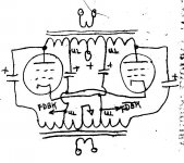
The Elliptron scheme below can provide 28% CFB using a standard 40% UL OT. Only a CT'd inductor is needed for DC current feed to the cathodes, rather than the full 2nd OT shown in the diagram below (ie, the full Crowhurst Twin version is shown).
--------------------------------------------------------------------
One issue with using the secondary output windings for CFB, is the phase shift from the leakage L between primary and secondary from loading. (same issue as for global N Fdbk) One needs an unloaded CFB winding to avoid this problem.
However, the amount of CFB NFdbk is typically so small from the secondary as to not matter in any case. But the secondary CFB approach seems somewhat futile for avoiding global N Fdbk deficiencies.
"You need to apply 20-30% of plate-to-plate swing to cathodes to have a meaningful effect, which means OPT with special feedback winding."
The Elliptron scheme below can provide 28% CFB using a standard 40% UL OT. Only a CT'd inductor is needed for DC current feed to the cathodes, rather than the full 2nd OT shown in the diagram below (ie, the full Crowhurst Twin version is shown).
--------------------------------------------------------------------
One issue with using the secondary output windings for CFB, is the phase shift from the leakage L between primary and secondary from loading. (same issue as for global N Fdbk) One needs an unloaded CFB winding to avoid this problem.
However, the amount of CFB NFdbk is typically so small from the secondary as to not matter in any case. But the secondary CFB approach seems somewhat futile for avoiding global N Fdbk deficiencies.
Attachments
Last edited:
Why 20-30% only? Go for 50% like McIntosh, then add positive feedback to bootstrap driver tubes! 😀
(just kidding, of course!) 🙂
My suggestion: try, listen, then decide, whether you like it, or not. The benefit of local feedback around output tubes is, softer clipping than with a global loop only. Plus, since OL gain is lower as the result, you can get better feedback on high frequencies, since need less compensation for stability. As you may see from my draft, there is no compensation added, like 390 pF, 82 pF, 18K in your amp.
Hi there, about 2 years back, i made a PP EL34 amp using EICO HF87 OPT and the RH Universal circuit. Essentially it was 2 rh amps per channel each amp driving the mirror image signals. For the phase splitter i used a Lundahl input/splitter transformer. I also used fixed bias to have the operating point adjustable via the bias voltage/current. The implementation was a success and the amp sounded good but for the effort and lowish power which was about 14 watts per channel I felt that it would probably be easier and sound better to just go with a SE KT120 amp. This i also built using the same power supply and as expected this turned out to sound better with more power.I was wondering if I could get rid of my global feedback and apply schade feedback to my dynaco st70. Output tubes are currently 6p3se russian. What would be involved and could it be applied? Here a pic of the schematic:
It is probably true the the PP EL34 could have used some tweaking, maybe a lot of massaging, but i found out what i wanted to in my build. And that is the driver stage needed to perform better to get better results. If you google RH Universal amp you will come to a lot of info about this amp. cheers.
Lets just repeat this again - don't use a triode driver in a Schade amp. You are asking for trouble. Pentodes, FET's or transformers are the only suitable drivers.
Shoog
Shoog
Lets just repeat this again - don't use a triode driver in a Schade amp. You are asking for trouble. Pentodes, FET's or transformers are the only suitable drivers.
Shade proposed a feedback around output tubes. Any feedback by voltage. If it is applied in series with input, there is no harm in triodes.
It's the same misery as CFA being no CFA 🙁
What is called Schade today isn't Schade at all 😡
Mona
What is called Schade today isn't Schade at all 😡
Mona
DIY Audio took very badly to Mr Alex Kitic. Looking back in time Mr Schade used the equally misnamed ( by others ? ) anode to anode feedback. As the anode isn't really available as an amplifiying input it really is the anode Rp of some devices is high enough to allow the ouput device anode to interact with that device input grid ( anode of output tube to it's own signal grid ). This makes another close copy of triode working. I think final Rp of the output device has a small advanatge over strapped triode. One example of Kitic said 900R over 1200R. Seeing how the gain drops over the usual way of working I wouldn't question it. It is very local feedback which can only be good. If one substitutes ECC82 for ECC81 in a Kitic circuit all remains remarkably similar. One is then left with asking which is best. The ECC82 stops the circuit working as described. Looking carefuly it says what one wins in one way is lost in an other. The ECC82 can be made into a cascode which would seem to be best of both worlds. Not least ECC82 is OK to work this way. It's hard to say if t is better than 1 x ECC81. If I did this I would configure my amp to swap tubes once a week. I would have reverse connections side to side. This might maximise tube life.
To my best understanding this " Schade "feedback was used in 1938 on the 807 beam tetrode and was useful to reduce higher harmonics not seen in triodes like PX25. 807 was and is a very remarkable device. Jack of all trades and master of none would be fair.
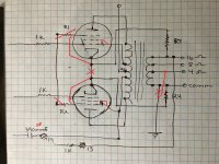
Here if I remember is an RCA design circa 1960. A TV tube had been upgrade to be a very high gain audio type 7199. It makes me think RCA sold Dynaco on a simple version. If you look carefully they are thinking along the lines of an ultimate Dynaco. From my own work I would not agree only a driver pentode works. I think it is a good place to start. The FET option could be very good. Cascode also. I have a feeling this is one of or mans designs.
Otto H. Schade - Wikipedia

To my best understanding this " Schade "feedback was used in 1938 on the 807 beam tetrode and was useful to reduce higher harmonics not seen in triodes like PX25. 807 was and is a very remarkable device. Jack of all trades and master of none would be fair.
Here if I remember is an RCA design circa 1960. A TV tube had been upgrade to be a very high gain audio type 7199. It makes me think RCA sold Dynaco on a simple version. If you look carefully they are thinking along the lines of an ultimate Dynaco. From my own work I would not agree only a driver pentode works. I think it is a good place to start. The FET option could be very good. Cascode also. I have a feeling this is one of or mans designs.
Otto H. Schade - Wikipedia
Whilst this is not exactly the same thing The Valve Wizard link proves anode to signal grid feedback is well known. One common example is a EF86 signal pentode with RIAA correction. Often if looked at carefully the component choices do not give 3180/318/75 uS. The reason is the gain of the device is not high enough especially above 10 kHz. This is a defect which even op amps suffer ( clicks sounding worse than they should as they need to cycle through the feedback loop ). The EF86 version can sound very OK ( Leak ). Of the types of feedback that can be used it is not bad. The EF86 is a very interesting device. I don't really trust modern versions enough to say they should be used. They seem very marginal as a driver device ( Quad ).
QUAD II Valve Power Amplifier Information
The Valve Wizard
QUAD II Valve Power Amplifier Information
The Valve Wizard
Nice RCA circuit with all kinds of feedback.From anode to grid feedback only power tube.Anode to cathode feedback over two tubes.Concertina feeback with cathode resistor and finaly global feedback to the cathode preamp (CFA ?)
No Schade here.Schade is input voltage minus feedback voltage to control grid, no input current.
With the feedback resistor anode to control grid there is no voltage from the feedback, control grid voltage is unchanged.If you drive such stage with a Z=0 driver there is no feedback at all.
A triode with its rather low Za has an easy job compared to a pentode to drive such an output stage.
Mona
But the driver is part of the feedback circuit in that it forms a voltage divider with the feedback resistor and grid resistor. For constant predicable feedback you want a constant rp value - which is what a pentode/fet offers and the opposite of what a triode offers. So what you get with a Kitic amp is variable feedback with signal - which cannot be good.
Shoog
Shoog
Here if I remember is an RCA design circa 1960. A TV tube had been upgrade to be a very high gain audio type 7199. It makes me think RCA sold Dynaco on a simple version. If you look carefully they are thinking along the lines of an ultimate Dynaco. From my own work I would not agree only a driver pentode works. I think it is a good place to start. The FET option could be very good. Cascode also. I have a feeling this is one of or mans designs.
Otto H. Schade - Wikipedia
This amp has nested feedbacks. Feedback to cathodes of driver tubes increase their output resistance.
Not impossible someone is trying matching that to the same kind of (inverted)distortion in the power tubes.
"Matching" idea comes from imagining subtracting of functions, like in the same stage of P-P amps, while in case of 2 stages they have to be multiplied!
Indeed, copy the inverted transfer of the output devided by it's gain.Won't"Matching" idea comes from imagining subtracting of functions, like in the same stage of P-P amps, while in case of 2 stages they have to be multiplied!
be perfect but it seems there are who try it.
Mona
Usually just 2nd Harmonic is all that cancels out in those complementary distortion schemes.
The RCA 50 Watt amplifier design has been somewhat enigmatic to me.
With three N Fdbk loops (2 nested ones, and one outer Global), the Schade like loop to the 6CB6 plate lowers the gain greatly for the loop to the 6CB6 cathode (by loading down the hi-Z 6CB6 plate). While the loop to the cathode is far more effective at reducing distortion (more potential loop gain).
Seems a waste of the cathode loop gain with both. However, the cathode loop does linearize the V to I conversion of the 6CB6, for the "Schade" loop up top, so it's hard to judge the overall net effect. But by lowering the high loop gain for the 6CB6 cathode loop, it is probably far more stable for DIY efforts being successful. This may be the reason it's that way, I don't know.
Joe Rasmussen in the thread "Modern Tube Amplifier Designs?" post #135 April 2007 mentions some experimenting with the two local loop types.
http://www.diyaudio.com/forums/tubes-valves/142246-modern-tube-amplifier-designs-14.html#post1809142
"the Anode-to-Anode (AA) loop pair was tried on its own and while it sort of worked it was also problematic in a different way. There was a great sense of clarity but also tended to sound lightish in balance. Then the Anode-to-Source (As) [ 6CB6 cathode here] loop pair was introduced and this had the exact opposite effect. If AS was balanced against AA, then the balance could be "dialled" in. If AS was allowed to dominate, then the sound would sound to rich and too dark and taking out AA alltogether and it would sound positively weird. "
Not exactly "technical" interpretations, and using a JFET/tube cascode instead of a pentode driver. But he said it was possible to balance the two loops for best results. Is the RCA design balanced by these criteria somehow?
The Citation II has a somewhat similar dual "local" (no OT in loop) N Fdbk loop arrangement, but both go back to the same driver grids. Both loops cannot be satisfied that way, so some type of balancing (of sound or distortion) must have taken place during design.
Last edited:
- Status
- Not open for further replies.
- Home
- Amplifiers
- Tubes / Valves
- Schade Feedback In A Push Pull Differential Amplifier?