Alex Kitic seemed to have many small changes of direction on the pentode g2 voltage. It is rather cute to use a zener if you follow his reasoning. Hopefully we wouldn't encourage a problem using two zeners if PP. Less so than UL causes problems I suspect. I imagine a series resistor could be added.
As we have AC Schade feedback and we have g2 voltage do we not have a poormans variable UL? The problem is the people who realish doing curves seem not to realish this circuit. I can live in hope. One advantage I can see over UL is if we use a resistor to set g2 we have a first order Rg2.g2 filter with hopefully no AC component. When UL we have a complex feedback path. Schade also is simpler for the AC part. What we might looose is gain or have higher output device Rp.
As we have AC Schade feedback and we have g2 voltage do we not have a poormans variable UL? The problem is the people who realish doing curves seem not to realish this circuit. I can live in hope. One advantage I can see over UL is if we use a resistor to set g2 we have a first order Rg2.g2 filter with hopefully no AC component. When UL we have a complex feedback path. Schade also is simpler for the AC part. What we might looose is gain or have higher output device Rp.
Hi Douglas
Check Philips or TFK EL34 datasheet for PP 100W in pentode mode , they suggest 800V/400V , even Tung Sol 6550 suggest 600V/300V for PP 100W ,
after all I have made two unit based on Philips/TFK application note , one was RF/AM modulator with 4xEL34(KT90) with 850V/425V and second was
one Marshall SL clone with 4xEL34 750V/375V , those EL34 last and last.
Regards
Have you drawn those load lines? Do you really want to use them? If so, do please show me why.
cheers,
Douglas
At that time I have no drawn any load lines , but that modulator and guitar amp works like charm for decades altogether with incredible output dynamics ,
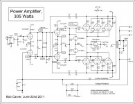
btw, recently I have noticed that B.Carver use similar approach(725V/345V) in his very powerful audio amps even exceeding power tubes (6550) max. voltage ratings suggested from tube manufacturer (600V/300V), why ?
btw, recently I have noticed that B.Carver use similar approach(725V/345V) in his very powerful audio amps even exceeding power tubes (6550) max. voltage ratings suggested from tube manufacturer (600V/300V), why ?
Attachments
Last edited:
That's for Class B operation, perhaps ok for PA applications, but not hi-fi...Check Philips or TFK EL34 datasheet for PP 100W in pentode mode , they suggest 800V/400V<snip>
Than can we say that Carver`s high power tube amps are not hi-fi but perhaps PA ?
Regardless to Philips or TFK app.note that says is class B operation for me personally it is still one very lean biased AB1 class of operation , since I consider that pure B class of operation is than when at zero input signal output power tubes are biased exactly at point where anodes currents stops to flow , Ia/Ia`=0mA.
Regardless to Philips or TFK app.note that says is class B operation for me personally it is still one very lean biased AB1 class of operation , since I consider that pure B class of operation is than when at zero input signal output power tubes are biased exactly at point where anodes currents stops to flow , Ia/Ia`=0mA.
I made no comment on Carver's amplifier which has a sliding bias scheme... For the Philips TFK example whether it's Class B, or lean biased Class AB1, it really does not matter, since neither is commonly associated with hi-fi reproduction, but if you like it, that's that...
Well banat, should you wish to find the required data, and then draw the load line, you will no doubt see why g2 voltage at a very particular level is important.
From what I have seen of Carver's SS stuff, I will not conclude any decision of his had to do with delivering the best sonics if they stepped on so much a mW of output power...🙂
cheers,
Douglas
From what I have seen of Carver's SS stuff, I will not conclude any decision of his had to do with delivering the best sonics if they stepped on so much a mW of output power...🙂
cheers,
Douglas
I like valves because they force us to look at what is really important. To be honest most of what valve lovers love means very little to me. The fact a voice is there in space makes them worth the belief. Very similar transistor designs sound very similar. The main problem with transistor designers seems to be they have to do it the standard way. This might even mean they have a job or don't have a job. When valve lovers say " don't you love that smell " I truely don't. I guess if I do love one device for it's looks when on it is the 807.
Here is some other thinking as the science says it is right ( link at page bottom ). This idea might cost pennies and answer a question. Here a transistor is an emitter-dyne phase splitter ( transistor cathodyne). It could go before a double Schade stage. I suspect it could be mildly better than lets say a ECC82 doing the same job. Myself, I would just use an ECC82 or 12BH7 voltage amp before, any second harmonic is useful. Here's a thought. If the 12BH7 voltage amp had an optional cathode capacitor it might be possible to have the gain needed for old style FM tuners. That would be ideal engineering. Better than an op amp to do it. There are so many valve choices, I am sure one will work.
http://www.r-type.org/pdfs/12bh7.pdf
Emitter-dyne. A MJE340 would do this job if using 270VDC rail. 3.6 mA looks fine. I suspect be it transistor or valve it will be Cathodyne or not Cathodyne that matters. If needed heat-sinked to the chassis it could give current well above the usual. Some MJE340 I bought were the insulated type, they could bolt up without any insulators. With some care a MPSA94 could be used if wanting more swing. There still seems to be many for sale. BF720 ( Old BF469? ) is the device many like. No heater to power into the bargain. In this application the transistor might be the better device even when only ears to convince.
https://assets.nexperia.com/documents/data-sheet/BF720_722.pdf
BTW. As far as I can see it's only long balanced lines that make a Cathodyne suspect. Also CMRR. There is a complex debate as to the output impedances. I think they forget to reference that as the signal does to it's nearest low impedance point.
Transistor phase splitter (Yaqin MC-84L)
One circuit I haven't seen is a transistor or enhancement FET long tail pair phase splitter. The advantage over a valve being a higher collector or drain output resistance than with a valve triode circuit. As this type of phase splitter is more likely to change the sound compared with the Alex Kitic SE designs the choice of component might be less the question than the circuit itself. One advantage that might be seen is enough gain with no extra devices. Hum rejection might be better than average. There is a small chance more is won by using transistors than is lost in a long tail type. I suspect an extra gain stage would be needed to shift the distortion balance.
Input Stage Distortion
I really like the idea of a Williamson input stage with part of it being transistor. Then 2 x Kitic RH34 in PP. The transistor should be as good 500 years from now as day one. It has a very easy DC connection to the input valve. It should make the testing very easy, just a DC test to transistor base and then DC on the ECC81 anodes and EL34 cathodes. If using a LM317 cathode biasing CCS have some small resistors to do a balance check. 1R at 60mA = 60 mV. Some mild imbalance might sound very nice, do listen before rushing to fit new valves.
To be clear. As the cathodyne type transistor phase splitter has a gain of 1 and -1 it is very unlikely to be very different to a triode valve circuit doing similar things. That should be true of a MOS FET also. It is just possible that the transistor is the device of choice in this example. The MJE340 possibly is more suited to a class A driver stage than it's modest specs say. I have found TO126 cased devices withstand 3/4 watt in free air and much more when on the chassis. That gives us plenty of drive current.
One circuit I haven't seen is a transistor or enhancement FET long tail pair phase splitter.
There are many examples of such design on Turner's site, such as:

There are many examples of such design on Turner's site......
Is that what Nigel meant??
If you are going to use SS for amplification, CASCODE mosfets have a constant input capacitance, and in comparison to useful pentodes, an infinite output impedance/'plate' resistance. You'll need three of course, one 'below' the source node, and two with the lower sources tied together LTP fashion...🙂
cheers,
Douglas
cheers,
Douglas
That's where I got to. What I thought would be common was a simple transistor long tail pair for a guitar amplifier. Op amp first stages are not unusual.
Although I have no workshop to use right now I feel I must try this idea. My first thoughts are the potential for voltage gain is massive and voltage swing also. By adjusting the voltage gain to where I need it to be the linearity should be excellent and also sensetivity. A fine balance between output impedance and linearity found one hopes if a Schade design. If I was modest in my current flowing MPSA44 could be used. My main concern is long tail pair or not long tail pair rather than device be it transistor or valve ( for now ). I could even do a pair of EL 34 in UL local feedback ( no loop feedback ) just driven by the long tail pair. As there is much harmonic cancellation in the coupling of the emitters I suspect the distortion would be mostly 3rd with a little 5th . I doubt I would love that, the output also. A simple triode input stage could be the answer.
An amplifer that comes to mind was the old AMC hybrid. The reason to do a hybrid is to have it questioning assumptions. Then again I have a warm spot for diesel locomotives as much as steam. My steam friends don't see the point of diesels.
Mostly to know if it is a possibility we could look at. The more I look at this I have doubts be it transistor or valve. I guess a 1960's design could have taken this route if the MJE340 was around. Doubtless with loop feedback. Having read much 1960's stuff it seems to me if distortion was below 0.1% at lets say 15 watts the job was seen to be done. The fact it might be all odd harmonic would be seen as unimportant. At the time the choice between valve and transistor was very equal where companies knew good sound quality. Given modern devices those transistor designs were rather good. Tobey Dinsdale and JLH designs come to mind. The JLH has almost no devices and almost no distortion. As JLH said not obviously different to the Williamson he built.
The Japanese said it was the quest for low distortion below the limits of perception that ruined transistor designs ( I see this still today, I am always surprised if a very low distortion design sounds open, they can ). It is said they had very different designs for the Japan market. Then the people who always are right gradually found words for things like slewing distortion and similar. To my way of thinking whatever makes a design simple and elegant with good specification must be a winner. The fact a set of valves can boil away day in day out in class A is most of the job done. It is said this high internal temperature is part of the magic.
The Japanese said it was the quest for low distortion below the limits of perception that ruined transistor designs ( I see this still today, I am always surprised if a very low distortion design sounds open, they can ). It is said they had very different designs for the Japan market. Then the people who always are right gradually found words for things like slewing distortion and similar. To my way of thinking whatever makes a design simple and elegant with good specification must be a winner. The fact a set of valves can boil away day in day out in class A is most of the job done. It is said this high internal temperature is part of the magic.
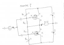
Nige and other members what do you think about this simple(simplified) complementary power bridge , is there Shade Fb or not?
ps, if moderator find that this post is off-topic it can be deleted , no hard feeling from me.🙂
ps, if moderator find that this post is off-topic it can be deleted , no hard feeling from me.🙂
Attachments
Last edited:
I have seen that used with a ECC88 driver stage I think. One idea I had was 500V cheap IRF MOSFET's in LTP. It sort of feels right if any LTP is right. Off topic isn't a problem if it looks to return to the topic. Mostly how to find the Schade Window.
Having given it much thought I can imagine in some ways Schade is the better feedback if it really did cure the weakness of the 807 over lets say a 2A3 circa 1937. That is to be most like a triode whilst having gain or impedance advantages. I could imagine Mr Schade was dubious about UL feedback. Not least as the output transformer designs would need to change to take advantage of how it could work. It is a bit of a black art to get it to work. I have recently hit a brick wall with a mains transformer design. The guy at the transfomer company was a bit shocked I solved the problem. I did it at very reasonable price also, regulation being 50% better than off the peg designs. I just pretended it was an output transformer. It's only downside is size which I sort of like, Big is Beautiful.
Having given it much thought I can imagine in some ways Schade is the better feedback if it really did cure the weakness of the 807 over lets say a 2A3 circa 1937. That is to be most like a triode whilst having gain or impedance advantages. I could imagine Mr Schade was dubious about UL feedback. Not least as the output transformer designs would need to change to take advantage of how it could work. It is a bit of a black art to get it to work. I have recently hit a brick wall with a mains transformer design. The guy at the transfomer company was a bit shocked I solved the problem. I did it at very reasonable price also, regulation being 50% better than off the peg designs. I just pretended it was an output transformer. It's only downside is size which I sort of like, Big is Beautiful.
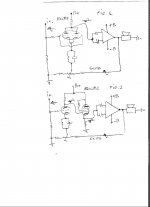
That inverting SS (Lat-Fet) power bridge can be driven in several ways , here`s couple simplified examples how that can be done ,
in fig.1 VAS/driver tube can be Ecc88 or even better Russian triode 6c45p ,
in fig.2 VAS/driver tube can be Ecl82 or similar triode/pentode tube , where triode part is VAS stage and triode strapped pentode part is buffer/ low output impedance driver tube .
from many reasons I prefer solution from fig. 2
(ps, dam`n broken TV`s and other consumer electronics which everyday repairing consume to much time from me , so no to much time left for so many very good DIY projects like this simple hybrid amp .)
Attachments
- Status
- Not open for further replies.
- Home
- Amplifiers
- Tubes / Valves
- Schade Feedback In A Push Pull Differential Amplifier?