

i have 6 feet long interconnects, i cannot detect any issues so far.Can the SCG drive two feet of interconnect or should the circuit be placed as close to the amplifier input as possible?
My four amplifiers are separate and it is impossible to place a stereo board intimately close to two amplifiers. I may need four boards if that is necessary.
All of this is dependent on getting LAZY SINGING BUSH pcbs. Hope ZM makes them available.
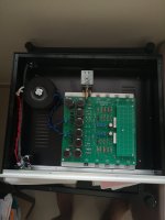
Very clean layout with all transistors mounted to the bottom. That’s one reason I put them there, thinking they could all be mounted to the bottom plate. Good to see that. Is that a second floating plate I see there? Very impressive!
have been listening to the preamp past few days, I must say that i am loving the preamp a lot. It has good drive and headroom, effortless and i am most impressed by the bass.
gain FET used is STP30N10F7. The midrange is smmmooth.... not sure if it is due to the 10m45 ccs as mentioned by ra7, has a tube-like quality to it. I have taken the current to 30ma as recommended by ra7 and this will make the preamp run hotter, so make sure heatsinking is adequate. In my system, the mu follower mod added some improvements not by a huge margin but it is discernible, i am getting a slightly more wider soundstage. even without the mu follower mod, i am experiencing very good sound. Now i am not sure if i would want to experiment with another FET eg.SIHP10N40D because the STP30N10F7 is sounding so good. Anyone tried rolling different gain FETs besides ra7 himself?
gain FET used is STP30N10F7. The midrange is smmmooth.... not sure if it is due to the 10m45 ccs as mentioned by ra7, has a tube-like quality to it. I have taken the current to 30ma as recommended by ra7 and this will make the preamp run hotter, so make sure heatsinking is adequate. In my system, the mu follower mod added some improvements not by a huge margin but it is discernible, i am getting a slightly more wider soundstage. even without the mu follower mod, i am experiencing very good sound. Now i am not sure if i would want to experiment with another FET eg.SIHP10N40D because the STP30N10F7 is sounding so good. Anyone tried rolling different gain FETs besides ra7 himself?
Schematic is posted. Round 1 PCBs are gone. I'm working on an update. Should be done this week. And then we'll have more.
Secure a board from ra7. I am sure you will be happy with it. I am using all industrial components nothing fanciful, and yet the sound is impressive.This looks like an interesting project. Are there PCBs or gerbers available?
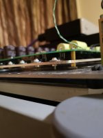
It is taking me a while to build, but I am making progress. The power supply check is complete and everything looks good. I did get nervous that something was not right in one of the channels. The instructions say to put the test lead on TP4. On the first channel on the left I got 126 volts, but when I connected the lead to TP4 on the
 right channel nothing. After some investigation the correct test point is actually TP5 on the other channel. I feel much better now. I need to wait for the caps to drain before soldering in the resistors.
Oh, I got the labeling wrong for the second channel. Thanks for catching that. Will add that to the list. Good to see your progress! Keep us posted.
Making good progress on the schematic and PCB revisions. Hope to post an update here soon.
Making good progress on the schematic and PCB revisions. Hope to post an update here soon.
Did you skip the input caps?It is taking me a while to build, but I am making progress. The power supply check is complete and everything looks good. I did get nervous that something was not right in one of the channels. The instructions say to put the test lead on TP4. On the first channel on the left I got 126 volts, but when I connected the lead to TP4 on theView attachment 1077805 right channel nothing. After some investigation the correct test point is actually TP5 on the other channel. I feel much better now. I need to wait for the caps to drain before soldering in the resistors.
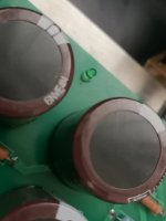
The input caps are the same Clarity caps and they are on the bottom. It was way too tight having both on top.Did you skip the input caps?
In my situation I do not think I will need any gain at all.
Does that mean there would be no positive feedback? From your comment within the thread that did not sound like zero gain was a problem.
(Of course, in my case all is dependent upon there being a Lazy Singing Bush set of pcbs becoming available)
Does that mean there would be no positive feedback? From your comment within the thread that did not sound like zero gain was a problem.
(Of course, in my case all is dependent upon there being a Lazy Singing Bush set of pcbs becoming available)
- Home
- Amplifiers
- Pass Labs
- Schade Common Gate (SCG) Preamp