Yeah, I can post it. Not at the computer right now but will do later.Looking forward to the new iteration!
I've been enjoying the fascinating progress of this excellent circuit. Will you be posting the updated schematic?
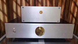
Glad to announce that my preamp has been completed. The smaller equipment on top is my Dorati Dac. They make a perfect marriage. i have to say it again, this preamp is sounding so good that i can listen to music for many hours.
Attachments

That is beautiful! Love that golden knob and the look! Just amazing!
And so happy to hear the positive impressions! That really makes my day
BTW, I have a Dorati too. I want to try it with a trafo for the IV.
And so happy to hear the positive impressions! That really makes my day
BTW, I have a Dorati too. I want to try it with a trafo for the IV.
Glad to announce that my preamp has been completed. The smaller equipment on top is my Dorati Dac. They make a perfect marriage. i have to say it again, this preamp is sounding so good that i can listen to music for many hours.
Nicely done! That looks great 🙂
IRF9640 listed by On as replacement
Attachments

Updated schematic. One channel shown. You could skip the trimmer in PS and connect the gate of the FET directly to the zener string.

Quick update: end of summer and school start have been very hectic the past few weeks. Made some progress this week with the layout. It is starting to come together. Hope everyone is doing great! Any new builds come to life (not just SCG)?
Any new builds come to life (not just SCG)?
I recently finished a pair of Pass Aleph 2 mono-blocks. These have what I consider to be a lowish input impedance of 10 Kohm. Would the SCG be fitting for this? Seems like I would want to lower the gain nevertheless.
SCG can drive that easily. How much gain does the Aleph 2 have, which speakers, and what are you using to drive it right now?I recently finished a pair of Pass Aleph 2 mono-blocks. These have what I consider to be a lowish input impedance of 10 Kohm. Would the SCG be fitting for this? Seems like I would want to lower the gain nevertheless.
SCG can drive that easily. How much gain does the Aleph 2 have, which speakers, and what are you using to drive it right now?
20 dB gain. The speakers are 85 dB or 99 dB depending on which I use (sorry, not very helpful). I am currently using ACP+ boards in a Yarra to drive the amps, which I think has a gain of 9 dB.
Here is the post with gain calculations. 11 db might be appropriate. I believe Commstech has set it up with about 10db gain. And maybe there is an F4 in your future and then you can set it up for more gain.
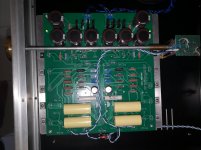
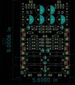
Here's what it is looking like. It is like a Led Zepp song--it comes out different every time. Though this one does bear resemblance to the previous one. The layout is tighter but it is still going to be a big board. Thoughts?
Could go tighter still with smaller 0.25W resistors, but I don't like boards that are very tight, or those that cannot be easily reworked. Still need to work on pad sizes and some other things on the list.

Could go tighter still with smaller 0.25W resistors, but I don't like boards that are very tight, or those that cannot be easily reworked. Still need to work on pad sizes and some other things on the list.
Looks pretty good so far Ra. I don’t think reducing the size of the resistors will save much space, the capacitors are the real estate hogs. But tweaking is a big part of the fun with SCG, decreasing the overall size of the board will also reduce component choices for builders. IMO, I’d rather have space for choices 🙂.
A suggestion, cut out the pcb behind the heatsinks to open up access to attach the mosfets to the baseplate. This will keep them mostly tucked under the pcb so they don’t add a lot of width to the overall footprint.
A suggestion, cut out the pcb behind the heatsinks to open up access to attach the mosfets to the baseplate. This will keep them mostly tucked under the pcb so they don’t add a lot of width to the overall footprint.
Attachments
Good points. Now I'm wondering what would happen if I simply deleted the heatsink footprints. The non-finned ones work just fine with the amount of heat to be removed from each device. Getting rid of that heatsink footprint would save a lot of space.
Would the cuts you are suggesting cost extra?
Would the cuts you are suggesting cost extra?
Last edited:
Very nice new layout.Here's what it is looking like. It is like a Led Zepp song--it comes out different every time. Though this one does bear resemblance to the previous one. The layout is tighter but it is still going to be a big board. Thoughts?
Could go tighter still with smaller 0.25W resistors, but I don't like boards that are very tight, or those that cannot be easily reworked. Still need to work on pad sizes and some other things on the list.
View attachment 1086439
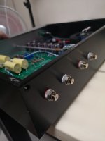
By adding these small individual heatsinks it’s much easier to assemble vs having to attach the devices at the bottom of the enclosure w pads and everything. It kind of reminds me of the ACA mini which was very easy to assemble.
My 2 cents
Eric
One can still use the little heatsinks even with the attachment posts not being there. This being DIY there is always a place for ingenuity. A small spacer underneath holds them steady as long as you are not going to ship them and even then it would not be hard to stabilize the assembly.. The cutaway would be an advantage. I am not worried about the cost but if it is surprisingly high then one could understand you not wanting to do that.
I would appreciate the larger board.
Looks like the resistors closest to the gates are much closer to the gates now - a good thing. I like those to be attached to the device just as we did with vacuum tubes at the socket. so now the end of the resistor not attached to the mosfet will not have too far to go to fit into its hole on the board. I know most of the folks who get the board will prefer to do it the way you have imagined it.
Now if ZM would offer his Lazy SB boards - but the mosfet he recommends is not to be available until March so I guess there is no need for him to be in a hurry - assuming he is going to offer them. Luckily a circuit easy enough to perfboard though his boards would be much better.
Thanks for your efforts!
- Home
- Amplifiers
- Pass Labs
- Schade Common Gate (SCG) Preamp