Since the technical question will start pretty soon should Rahul create a building thread for the SCG preamp or do we continue here ?
Yes 🙂Since the technical question will start pretty soon should Rahul create a building thread for the SCG preamp or do we continue here ?

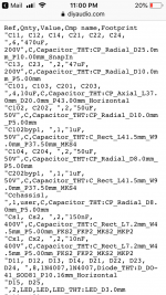
Attached is a schematic PDF and a text file (CSV format) showing the footprints used in KiCAD. The schematic has a few notes. Hopefully, this is enough to get you started. I am also preparing the parts list and a write-up on the schematic and power up, but that will take a bit of time.
Attachments
Hi RahulAttached is a schematic PDF and a text file (CSV format) showing the footprints used in KiCAD. The schematic has a few notes. Hopefully, this is enough to get you started. I am also preparing the parts list and a write-up on the schematic and power up, but that will take a bit of time.
Is it possible to also have the first file in PDF, attached file is what I see when I open it.
Thanks
Attachments
demando montalban! 😉Hi Rahul
Is it possible to also have the first file in PDF, attached file is what I see when I open it.
Thanks
No clue what this means...
I don’t need it personally since I always select my components once I have my PCB.
I don’t need it personally since I always select my components once I have my PCB.
would-it be possible to mod this preamp as a real amp to drive high sensitivity speakers (8 or 16 ohm easy to drive)??
use a beefier Mu-Follower and increase the bias?
Or a choke instead of the Mu-Follower ?
use a beefier Mu-Follower and increase the bias?
Or a choke instead of the Mu-Follower ?
I am working on exactly that. New chassis parts ordered. But will wrap-up the GB first.
I want to run it with a choke, otherwise the dissipation requirments get quite large, though still very much within the capability of monoblock 3U or 4U. George is taking a different approach with high voltage and low current and a trafo as the load. Should be fun both ways
I want to run it with a choke, otherwise the dissipation requirments get quite large, though still very much within the capability of monoblock 3U or 4U. George is taking a different approach with high voltage and low current and a trafo as the load. Should be fun both ways
To paraphrase an old movie, "Parts list? We don't need no stinkin parts list!" This design is similar to the input stage in my UNSET amp design which uses vacuum tubes for the gain stage. The P-Fet and CCS / Mu-Follower are mosfet based. I have always wondered how a solid state gain stage would sound. There is a perf board prototype solid state gain stage around here somewhere. It was used for curve tracing. These boards will just make the job a bit easier. One board will be a preamp not too different from what has been discussed throughout this thread. I have several dozen different solid state devices to try in it. The second board will be the power amp. Initial experiments will be similar to the original vacuum tube design, which uses a vacuum tube style OutPut Transformer. I have several OPT's to try from 600 ohms up to 5000 ohms which will be targeting power output levels in the 20 to 30 watt range on B+ voltages from 250 to 600 volts. Initial testing will use lab type bench power supplies.George is taking a different approach with high voltage and low current and a trafo as the load. Should be fun both ways
If I blow up all of my available HV rated parts stash, or don't like the results, then I'll look into direct speaker drive using a CCS / Mu-follower with an agile (modulated) drain supply for efficiency improvement to reduce the heat sink size requirement. I gave away my 5H at 5Amp chokes when I had to move everything I owned 1200 miles on 3 weeks notice.
Just noticed that Schade resistors are different for each channel on the latest schematic and this is repeated opn the parts list.
The original values are given (1k, 10K) for the circuit on the left side of the page and the new values of 10/100k for the circuit on the right side.
Any further thoughts on what values are best to start with? I am ordering 10k/100K - but since I want one-half of the gain I am ordering 50K/100K.
The original values are given (1k, 10K) for the circuit on the left side of the page and the new values of 10/100k for the circuit on the right side.
Any further thoughts on what values are best to start with? I am ordering 10k/100K - but since I want one-half of the gain I am ordering 50K/100K.
I should have paid more attention when I was making the .pdf.
I notice the same kind of thing with RV102 and RV202, 10K and 100K, respectively.
When i "cleaned up" the parts list i was not paying close attention.
Today I am making my order and looking closely. I hope you know I have no desire to play gotcha - just trying to be of use.
THANKS!
I notice the same kind of thing with RV102 and RV202, 10K and 100K, respectively.
When i "cleaned up" the parts list i was not paying close attention.
Today I am making my order and looking closely. I hope you know I have no desire to play gotcha - just trying to be of use.
THANKS!
- Home
- Amplifiers
- Pass Labs
- Schade Common Gate (SCG) Preamp