I sure can measure FFT but I think the mic is not calibrated not only about db but also in frequency range. It s my opinion cause since 5khz measured reaponse starts to drop.
Anyway, we have frd and zma files on half space, maybe we should work on that. Right now only tweeter needs an adjustement. Maybe in the spl and to fill that dip on 2khz.
Anyway, we have frd and zma files on half space, maybe we should work on that. Right now only tweeter needs an adjustement. Maybe in the spl and to fill that dip on 2khz.
Cucicu,
Ok I understand, no problem.
What I can do from my side, is making you a Butterworth 3rd order (B3) filter at 2kHz. I had it already finished with the Leap SPL's, very flat SPL. I can rework it using the Zaph free space woofer response and the Leap tweeter response. A B3 filter will give more power between 1 and 2kHz, that you are missing with the LR4 IMO. Maybe give it a try.
In previous designs I have a very good experience with B3 filters but I don't apply it as a rule.
The frd's you are mentioning to use are not half space, but infinite baffle responses. So you have to add the baffle response first. It is more easy to use the Zaph woofer response, it is baffle response included.
What do you think?
Using the half space response as you propose is not a solution because the coil in the woofer circuit would be much smaller and phase response would differ from the real one. If you have poor phase tracking,the frequency response around the crossover would feature dips and peaks. Also, the nearfield measurement does not include the baffle effects which need to be masked in the crossover.
I have had the best results with Linkwitz-Riley on the 18W woofer, the earlier rolloff of the transfer function clears some of the midrange rising response. This woofer works fantastic with 2nd order LR at around 2Khz.
I have had the best results with Linkwitz-Riley on the 18W woofer, the earlier rolloff of the transfer function clears some of the midrange rising response. This woofer works fantastic with 2nd order LR at around 2Khz.
Paul, Mario
Thanks both
I wanna try both the solution, if you want to share it.
The frd i attached are taken from dibirama, an italian site. You can register a free account an download many speakers. It reports measuremente are taken on infinite baffle
Regards
Thanks both
I wanna try both the solution, if you want to share it.
The frd i attached are taken from dibirama, an italian site. You can register a free account an download many speakers. It reports measuremente are taken on infinite baffle
Regards
can you post some values for coil and for LR?Using the half space response as you propose is not a solution because the coil in the woofer circuit would be much smaller and phase response would differ from the real one. If you have poor phase tracking,the frequency response around the crossover would feature dips and peaks. Also, the nearfield measurement does not include the baffle effects which need to be masked in the crossover.
I have had the best results with Linkwitz-Riley on the 18W woofer, the earlier rolloff of the transfer function clears some of the midrange rising response. This woofer works fantastic with 2nd order LR at around 2Khz.
I have no experience with the 8 ohm version, only with the 4 ohm one. Something like 2.7mH and 3.3-4.7uF should get you close there. The tweeter would need a 3rd order electrical for good phase tracking, there I cannot guess. The tweeter can be simulated.
I have no experience with the 8 ohm version, only with the 4 ohm one. Something like 2.7mH and 3.3-4.7uF should get you close there. The tweeter would need a 3rd order electrical for good phase tracking, there I cannot guess. The tweeter can be simulated.
Mario,
When you find it ok, I shall make the LR2 design too.
Cucicu,
I shall make 3 designs LR4, LR2 and B3 at 2000Hz.
I will use the Zaph measurement for the woofer and the Leap tweeter response. I create the woofer phase response with a minimum phase transform. It is not perfect but a good approximation in the operating range of the driver. Not for the outband, but I don't have the frd of the free field measurement now.
Is that ok for you? It is your speaker 🙂.
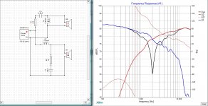
Have a look at the attached simulation. This is a simplistic crossover at 2Khz based on the .frd files you have uploaded. Tweeter should be connected with reverse polarity, otherwise you`d get the dip in black seen on the graph. If you want more baffle step compensation, increase L1 and R1 accordingly.
Attachments
Last edited:
To start with, LR4 2000Hz
Schematic filter 09

2.7mH is too large to realize a flat SPL.
2.2mH / 0.30E chosen
SPL and LR4 targets filter 09

Phase filter 09

blue is woofer; red is tweeter
In the drivers outband it can be designed better on target with even better phase aligning, but the schematic has to become more complicated then.
I have chosen now an offset of 20mm between the acoustic centers of woofer and midrange (woofer 20mm behind).
Schematic filter 09
2.7mH is too large to realize a flat SPL.
2.2mH / 0.30E chosen
SPL and LR4 targets filter 09
Phase filter 09
blue is woofer; red is tweeter
In the drivers outband it can be designed better on target with even better phase aligning, but the schematic has to become more complicated then.
I have chosen now an offset of 20mm between the acoustic centers of woofer and midrange (woofer 20mm behind).
Nice! I will try both.
Since i have simulated troels crossover with this driver, offset of woofer seem to be 24mm for a perfect reverse null phase allignement.
Paul do i wait for you to share the other filters? Tomorrow I have to put an end ro this story 🙂
Since i have simulated troels crossover with this driver, offset of woofer seem to be 24mm for a perfect reverse null phase allignement.
Paul do i wait for you to share the other filters? Tomorrow I have to put an end ro this story 🙂
Nice! I will try both.
Since i have simulated troels crossover with this driver, offset of woofer seem to be 24mm for a perfect reverse null phase allignement.
Paul do i wait for you to share the other filters? Tomorrow I have to put an end ro this story 🙂
Cucicu, not for today anymore.
Have a look at the attached simulation. This is a simplistic crossover at 2Khz based on the .frd files you have uploaded. Tweeter should be connected with reverse polarity, otherwise you`d get the dip in black seen on the graph. If you want more baffle step compensation, increase L1 and R1 accordingly.
Forgot something important - DCR of the parallel coil in the tweeter (L2) should be 1-1R4. 1R4 works best, coil will also be cheap as wire would be thin. If you don`t have such coil, add a resistor in series with it to achieve 1R4. DCR of L1 is 0.6 ohms, standard 1.2mm coil would be around this figure.
Forgot something important - DCR of the parallel coil in the tweeter (L2) should be 1-1R4. 1R4 works best, coil will also be cheap as wire would be thin. If you don`t have such coil, add a resistor in series with it to achieve 1R4. DCR of L1 is 0.6 ohms, standard 1.2mm coil would be around this figure.
I will try it tomorrow.
So, it means that the values of L1 and R1 go together.
Very interesting. Thanks !
So, it means that the values of L1 and R1 go together.
Very interesting. Thanks !
Yes and no. Increasing L1 means you get more baffle step compensation but this has a limit. Increasing R1 is to compensate the woofer baffle step loss incorporated in the inductor + higher voltage sensitivity of the tweeter. So, if you apply more baffle step, you`d need to pad the tweeter more. I hope that explains it.
Ok very claryfing.
I suspect that baffle step compensation with 2.7mh could be more than needed because until now I have tried 2.7mh with a lot of tweeter padding (not less than 3.3ohm and 22ohm parallel Lpad). So may be this causes a dip in the entire FR that makes basses (not involved in baffle step ) to be more present than other frequencies an so the backward sound of the speaker.
I suspect that 2.2mh is more adeguated but with a less quote of padding on tweeter. I will try in the morning.
but, i f you look at the EKTA 3 way simulated response (same baffle than actual, different positioning of driver, that is a 3 way, of course!) and you just consider the level of the single drfivers, you'll see that 2.7mh/47uf is used on the 18w8531 and put it to an SPL of ca.85db. All the mid section is 1-2db down and the tweeter response is 1-2db down (but we know Troels usally make a decrescent FR on the highs).
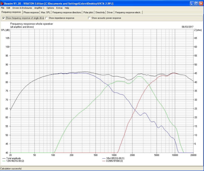
Right now, when we make the same system in a 2 way, on the same baffle, the LR4 on 2000Hz with 2.7mH/10uf put all the bass section down to 84-83db with a very smooth 1db slope from 100Hz to 1500hz. Tweeter filter is exactly the same on both simulations. So it looks like the baffle step compensation is a lot. Obviously, you should consider the different directivity and beaming beetween the 18w in the 2 way system and the 4" midwoofer employed in the 3 way system, but I think that 2.7mH is a lot and the response regarding basses is not flat.
what do you think?
I suspect that baffle step compensation with 2.7mh could be more than needed because until now I have tried 2.7mh with a lot of tweeter padding (not less than 3.3ohm and 22ohm parallel Lpad). So may be this causes a dip in the entire FR that makes basses (not involved in baffle step ) to be more present than other frequencies an so the backward sound of the speaker.
I suspect that 2.2mh is more adeguated but with a less quote of padding on tweeter. I will try in the morning.
but, i f you look at the EKTA 3 way simulated response (same baffle than actual, different positioning of driver, that is a 3 way, of course!) and you just consider the level of the single drfivers, you'll see that 2.7mh/47uf is used on the 18w8531 and put it to an SPL of ca.85db. All the mid section is 1-2db down and the tweeter response is 1-2db down (but we know Troels usally make a decrescent FR on the highs).
Right now, when we make the same system in a 2 way, on the same baffle, the LR4 on 2000Hz with 2.7mH/10uf put all the bass section down to 84-83db with a very smooth 1db slope from 100Hz to 1500hz. Tweeter filter is exactly the same on both simulations. So it looks like the baffle step compensation is a lot. Obviously, you should consider the different directivity and beaming beetween the 18w in the 2 way system and the 4" midwoofer employed in the 3 way system, but I think that 2.7mH is a lot and the response regarding basses is not flat.
what do you think?
Last edited:
Cucicu,
Here are three designs for your project.
The LR2 2000Hz proposal Mario Pankov, a LR4 2000Hz and a B3 2000Hz.
I have used the Leap infinite baffle response for the woofer and applied a baffle response transform on it with the Jeff Bagby diffraction calculator.
In this way the woofer SPL is almost conform the Zaph measured curve.
For the tweeter I still use the Leap simulation.
All my SPL's and impedance values are based on the specification values of the drivers. So yours can be different.
The results.
Baffle response at 3m according to Jeff Bagby

Schematic filter 10 LR2 2000Hz proposal Mario Pankov

SPL filter 10 LR2 2000Hz proposal Mario Pankov

Schematic filter 11 LR4 2000Hz

SPL filter 11 LR4 2000Hz

Schematic filter 12 B3 2000Hz

SPL filter 12 B3 2000Hz

All the SPL's are simulated with no offset between the acoustic centers of woofer and tweeter.
With the woofer 24mm behind, there will appear some SPL dip around 8kHz, but acceptable and only at 0 degree on axis.
Here are three designs for your project.
The LR2 2000Hz proposal Mario Pankov, a LR4 2000Hz and a B3 2000Hz.
I have used the Leap infinite baffle response for the woofer and applied a baffle response transform on it with the Jeff Bagby diffraction calculator.
In this way the woofer SPL is almost conform the Zaph measured curve.
For the tweeter I still use the Leap simulation.
All my SPL's and impedance values are based on the specification values of the drivers. So yours can be different.
The results.
Baffle response at 3m according to Jeff Bagby
Schematic filter 10 LR2 2000Hz proposal Mario Pankov
SPL filter 10 LR2 2000Hz proposal Mario Pankov
Schematic filter 11 LR4 2000Hz
SPL filter 11 LR4 2000Hz
Schematic filter 12 B3 2000Hz
SPL filter 12 B3 2000Hz
All the SPL's are simulated with no offset between the acoustic centers of woofer and tweeter.
With the woofer 24mm behind, there will appear some SPL dip around 8kHz, but acceptable and only at 0 degree on axis.
WOW PAul, great job, thank you!
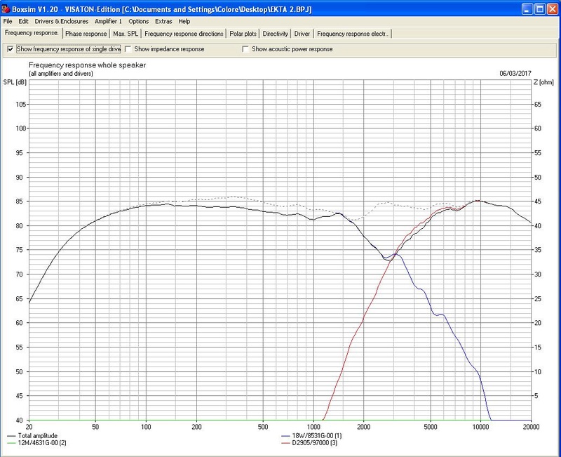
I'm listening right now to filter 11 LR4, I think we are on goal but there is an excess of mids from the tweeter...
18W sounds sweet, I think Baffle step is right with 2.2mH.
The tweeter is very "present" and lively in the 1-3khz zone, i think it could depend on the bump on 2khz. have a look:

I know it seems a little thing, but in reality this issue makes the tweeter sounding too midy and make mids forward.
Here troels says d2905 has a bump on 2khz and a dip on 3.5khz and thus need some equalizing, but I think we can work adding a resistor to the inductor of the tweeter or reducing 10uf cap to 8.2uf...what do you propose?
I'm listening right now to filter 11 LR4, I think we are on goal but there is an excess of mids from the tweeter...
18W sounds sweet, I think Baffle step is right with 2.2mH.
The tweeter is very "present" and lively in the 1-3khz zone, i think it could depend on the bump on 2khz. have a look:
I know it seems a little thing, but in reality this issue makes the tweeter sounding too midy and make mids forward.
Here troels says d2905 has a bump on 2khz and a dip on 3.5khz and thus need some equalizing, but I think we can work adding a resistor to the inductor of the tweeter or reducing 10uf cap to 8.2uf...what do you propose?
Last edited:
Yes, try C8 = 8.2 uF.
You can also try C8 = 8.2 uF and R1 = 3 Ohm. Or even R1 = 3.3 Ohm, you have to listen.
It is possible also your tweeter is playing a little louder than the specification shows.
SPL filter 11 C8 = 8.2uF

SPL filter 11 C8 = 8.2uF and R1 = 3 Ohm

You can also try C8 = 8.2 uF and R1 = 3 Ohm. Or even R1 = 3.3 Ohm, you have to listen.
It is possible also your tweeter is playing a little louder than the specification shows.
SPL filter 11 C8 = 8.2uF
SPL filter 11 C8 = 8.2uF and R1 = 3 Ohm
I think it is better also to increase C10 to 22uF.
C10 = 18uF causes some resonant boost in the electrical response at 3kHz.
You can see that in the impedance curve.
Try out some combinations based on listening.
Technical C8 = 8.2uF R1 = 3Ohm and C10 = 22uF seems to be the best.
Adding serial resistor with coil is not good in simulation.
SPL filter 11 C8 = 8.2uF R1 = 3Ohm and C10 = 22uF
Last edited:
- Home
- Loudspeakers
- Multi-Way
- Scan-Speak crossover help