But if you think Zaph is not applying bafflestep, you are dreaming.
Hi Steve,
I agree with your statement. In the Zaph ZRT measurement the SPL is 85 dB at 100Hz. For a woofer which has a SPL level of 87 dB at 100Hz on infinite baffle, the SPL level cannot be 85dB in free space.
The published Zaph ZRT measurement is not correct for low frequencies. The SPL level has to be lower below 400Hz.
Ok Paul, filter06 sounds damn good!
We have only to equalize bump at 2khz, dip a 2.5khz and 3khz of tweeter. Troels made this adding a LR but I m not able to do it.
Look here
www.troelsgravesen.dk/W1500_97
We have only to equalize bump at 2khz, dip a 2.5khz and 3khz of tweeter. Troels made this adding a LR but I m not able to do it.
Look here
www.troelsgravesen.dk/W1500_97
Ok Paul, filter06 sounds damn good!
We have only to equalize bump at 2khz, dip a 2.5khz and 3khz of tweeter. Troels made this adding a LR but I m not able to do it.
Look here
www.troelsgravesen.dk/W1500_97
Hi Cucicu
That is great news. It means that if the SPL is designed flat for this speaker, its sound is also good.
I think filter 05 is even better, I mean technical, you have to listen.
Concerning the equalizing of the tweeter, at first I have to simulate the tweeter response on its correct position. The ripple on the SPL will be different then.
SPL diffraction errors are dependent on the horizontal angle. So they are difficult to equalize or even cannot be equalized.
Afterwards I will do that in the best way.
Last edited:
In the Zaph ZRT measurement the SPL is 85 dB at 100Hz. For a woofer which has a SPL level of 87 dB at 100Hz on infinite baffle, the SPL level cannot be 85dB in free space.
The published Zaph ZRT measurement is not correct for low frequencies. The SPL level has to be lower below 400Hz.
Accurate low frequency measurements are difficult, indeed. I know only one designer who publishes correct bass response curves. That's Zaph! 😀
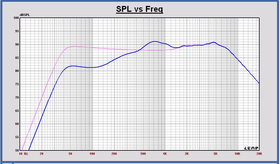
Let's do a proper calculation for the ZRT at 100 Hz. Driver SPL is 87 dB. The port contributes 0.6 dB and the filter transfer function another 0.9 dB. Hence we are at 88.5 dB. The baffle step at 100 Hz in 1 meter distance is -4 dB. So the result is 84.5 dB, and that's exactly what Zaph measures.
According to your chart LEAP predicts a baffle step loss of 7.5 dB at 100 Hz. That's very unlikely to be true. More than 6 dB simply is not possible IMO, and at 100 Hz and 1 meter it is less for sure.
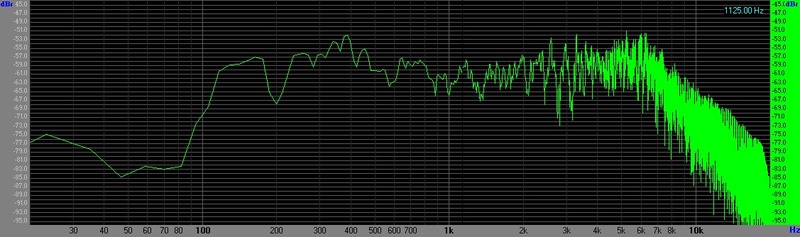
this is a measurement I have made, no calibrated mic, 1mt , center position between woofer and tweeter.
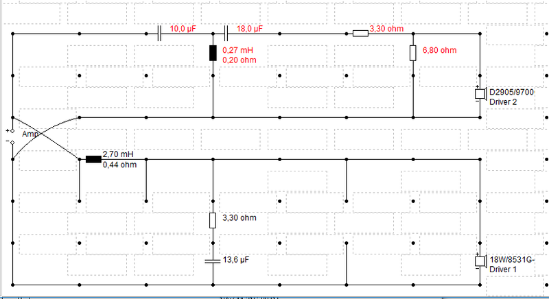
this is the crossover
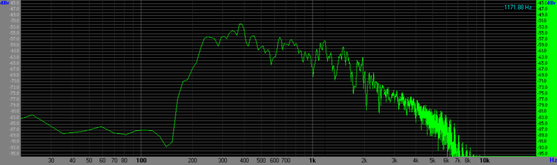
and this is only the woofer
it seems the woofer has two peaks at ca. 1175hz and 1600hz. may be that is the issue, because also with notch filter, or with the xover 05 suggested by Paul, listening is always too midy. what do you think ?
this is the crossover
and this is only the woofer
it seems the woofer has two peaks at ca. 1175hz and 1600hz. may be that is the issue, because also with notch filter, or with the xover 05 suggested by Paul, listening is always too midy. what do you think ?
Accurate low frequency measurements are difficult, indeed. I know only one designer who publishes correct bass response curves. That's Zaph! 😀
Let's do a proper calculation for the ZRT at 100 Hz. Driver SPL is 87 dB. The port contributes 0.6 dB and the filter transfer function another 0.9 dB. Hence we are at 88.5 dB. The baffle step at 100 Hz in 1 meter distance is -4 dB. So the result is 84.5 dB, and that's exactly what Zaph measures.
According to your chart LEAP predicts a baffle step loss of 7.5 dB at 100 Hz. That's very unlikely to be true. More than 6 dB simply is not possible IMO, and at 100 Hz and 1 meter it is less for sure.
Hi Dissi
Ok, when it is correct I have to agree. I did not taken into account the contribution of the filter and the port in my statement. But these two values are included in the SPL of the design with the filter. I only have some doubts of only -4dB loss at 100Hz in free space for this small cabinet. But also the Leap value of -7.5dB is not correct. Remark, that there is the path length difference between port and driver at 100Hz, which gives some SPL reduction on axis.
The problem with Leap is that it simulates different low frequency SPL values dependent on the complexity and shape of the cabinet, I did know that. Also for closed box systems it is the case. I am surprised about the -7.5dB Leap value at 100Hz for this rather simple cabinet shape now . I didn't have an exact view on that value now, that is the mistake I made.
To conclude, the error in the design with filter at 100Hz, should be 3.5dB with your statement of only -4dB loss due to the baffle. I will have a closer look of the influence of the path length diiference of the port and the driver. I think the loss is a little more than -4dB.
Last edited:
Mario,
I agree but you are speaking now about SPL values on and off axis in your comment and not about total power.
The power response is the total radiated energy on- and off-axis, or the on- and off-axis frequency responses. Thus, if you have a problem in the on-axis frequency response and the off-axis frequency response, let`s say to 60 degrees off-axis, these frequency responses would be reflected by walls and nearby boundaries summing at the listening position, some with higher delay than others. If you have a serious ripple on and off-axis they`d sum and produce a new combined ripple response which would be highly dependend on your listening position relative to the loudspeakers. This was my point. The baffle ripple is still serious even at 45 degrees, measure it for yourself on a standard rectangular baffle and you`d see.
On the topic now, if you didnt` like the Ekta too, perhaps the Revelator is not your driver. When things get to expensive stuff, its more about taste than drive unit capabilities. It also depends greatly on what sound system you listened before to audition the Ekta or your own new project. If you got used to the sound of hard cones, especially if used incorrectly, you may not like the paper scans a they sound mellow. In my opinion, more natural as well. Our hearing calibrates and if you expose it to a sound source with a specific sound signature for a prolonged period, other sources, even if better and more natural sounding, may sound weird to you.
Besides, you have spent EUR1000+ on drivers, why not spend an extra EUR100 and buy some entry level measurement system? Even if not calibrated, it would produce better results than what you have now.
this is a measurement I have made, no calibrated mic, 1mt , center position between woofer and tweeter.
it seems the woofer has two peaks at ca. 1175hz and 1600hz. may be that is the issue, because also with notch filter, or with the xover 05 suggested by Paul, listening is always too midy. what do you think ?
Cucicu,
Is this is an averaged FFT measurement with noise in your room?
Cucicu,
Is this is an averaged FFT measurement with noise in your room?
yes it is
The power response is the total radiated energy on- and off-axis, or the on- and off-axis frequency responses. Thus, if you have a problem in the on-axis frequency response and the off-axis frequency response, let`s say to 60 degrees off-axis, these frequency responses would be reflected by walls and nearby boundaries summing at the listening position, some with higher delay than others. If you have a serious ripple on and off-axis they`d sum and produce a new combined ripple response which would be highly dependend on your listening position relative to the loudspeakers. This was my point. The baffle ripple is still serious even at 45 degrees, measure it for yourself on a standard rectangular baffle and you`d see.
Ok Mario, I agree. Such bafflestep boost has to be compensated for sure.
I only would say that filtering the baffle boost will affect your total radiated power also. In that way it is better to design a cabinet with less baffle boost.
yes it is
This is again a new filter you are playing with. Is it better than filter 06?
Because you said that filter 06 was "damn good".
Difficult to follow this design path with simulations.
To make a good design, at first a technically maximal flat design should be made, based on good measurements. That should be the reference design to start with. And afterwards do some tweaking based on listening tests and check in simulation. But I understand your situation also.
I have to look at first to the low frequency response at 100Hz after some correct remarks of Dissi. I guess I have to do a correction there of about 1.5dB more. Then I will do the simulation of your last filter and compare with your measurements above 300Hz. Below 300Hz you probably measure some room response also.
Hi Dissi
Ok, when it is correct I have to agree. I did not taken into account the contribution of the filter and the port in my statement. But these two values are included in the SPL of the design with the filter. I only have some doubts of only -4dB loss at 100Hz in free space for this small cabinet. But also the Leap value of -7.5dB is not correct. Remark, that there is the path length difference between port and driver at 100Hz, which gives some SPL reduction on axis.
The problem with Leap is that it simulates different low frequency SPL values dependent on the complexity and shape of the cabinet, I did know that. Also for closed box systems it is the case. I am surprised about the -7.5dB Leap value at 100Hz for this rather simple cabinet shape now . I didn't have an exact view on that value now, that is the mistake I made.
To conclude, the error in the design with filter at 100Hz, should be 3.5dB with your statement of only -4dB loss due to the baffle. I will have a closer look of the influence of the path length diiference of the port and the driver. I think the loss is a little more than -4dB.
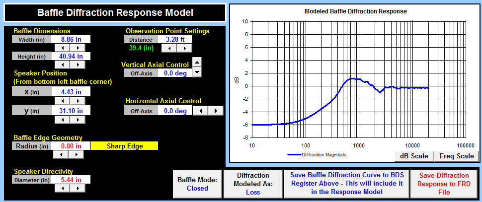
This is the baffle response of the system without port, so it is closed box; to avoid the discussion of the port position and impact on SPL.

Leap still simulates a roll off to -7.5dB, which is not correct indeed. IMO it has to be -6dB. I will do a correction on this.
@ Dissi
Why do you think the loss is only -4dB? For this small enclosure the baffle reponse is completely worked out at 100Hz.
yes, below 300Hz is the room but I don't mind about it, bass response is ok to my ears.
I ask you to reset everything and just consider this filter I'm trying right now, it's very equilibrated in the "boost" region (I think it's good baffle-step compensated) but mid-highs are a little backwards; I think this may depends on tweeter itself and on its placing on baffle. I think we should work only on tweeter to make sound it clearer, trying some equalization and playing with resistors values.
Referring to my listening experience, to my personal tastes and to the actual equipment/listening room, the actual filter is something like "flat", it has no any boost at a particular frequency, bass, mid and highs are equilibrated. So I think we have a "flat" target on which work on. But..... I'm listening to a "boring" sound, it has no character and lacks the "sparkle" of the best performer.
I feel it lacks something on the 2Khz-10khz range, something like "clarity", and "breath".
I tried many configs leaving the woofer out of games (2,7mH/12uF is almost perfect) and the actual situation is the one with the best equilibrium between the drivers. Modifying a cap or a resistor I have noticeable boosts/dips and mismatching with the woofer. So this is flat for me.
I'm sorry for all this, but I hope you would continue to help me.
regards
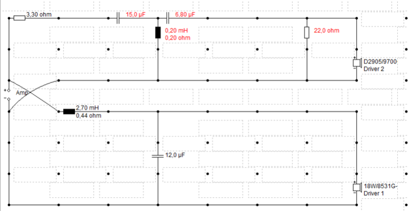
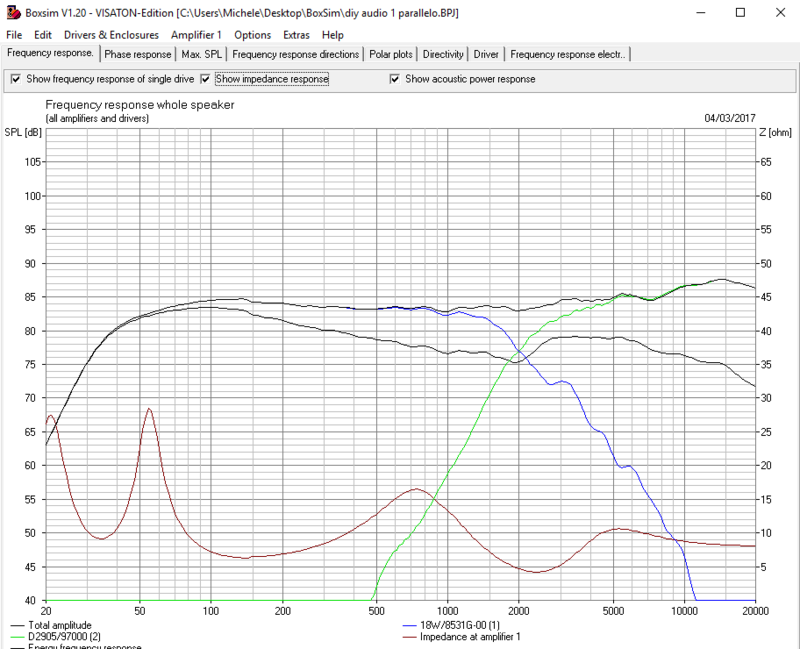
here's actual xover attachment and simulator response:
I ask you to reset everything and just consider this filter I'm trying right now, it's very equilibrated in the "boost" region (I think it's good baffle-step compensated) but mid-highs are a little backwards; I think this may depends on tweeter itself and on its placing on baffle. I think we should work only on tweeter to make sound it clearer, trying some equalization and playing with resistors values.
Referring to my listening experience, to my personal tastes and to the actual equipment/listening room, the actual filter is something like "flat", it has no any boost at a particular frequency, bass, mid and highs are equilibrated. So I think we have a "flat" target on which work on. But..... I'm listening to a "boring" sound, it has no character and lacks the "sparkle" of the best performer.
I feel it lacks something on the 2Khz-10khz range, something like "clarity", and "breath".
I tried many configs leaving the woofer out of games (2,7mH/12uF is almost perfect) and the actual situation is the one with the best equilibrium between the drivers. Modifying a cap or a resistor I have noticeable boosts/dips and mismatching with the woofer. So this is flat for me.
I'm sorry for all this, but I hope you would continue to help me.
regards
here's actual xover attachment and simulator response:
I'm sorry for all this, but I hope you would continue to help me.
regards
Cucicu,
No problem at all, I only would say how my favourite WOW is 🙂.
I think the goal of this forum has to be, to give the best support to each other.
I will simulate your last status and do some analysis of your measurements.
First I will do the low frequency SPL correction.
In your simulation I see that the impedance peak is 27 Ohm at 55Hz. I have 55 Ohm in my simulation. Have you also measured the impedance of the woofer in the cabinet without filter? If it is 27Ohm I have to make that correction also.
@ Dissi
Why do you think the loss is only -4dB? For this small enclosure the baffle reponse is completely worked out at 100Hz.
My simulation says -4 dB at 1 m and -5 dB at 10 m. Baffle step diminishes in the near field. Lojzek's simulation apparently says -5 dB at 1 m:
The baffle of a floorstander isn't exactly small. At least the height is close to 30% of the wavelength at 100 Hz, probably enough to have some impact.
Edge diffraction is very complicated and the different models used in simulation programs actually just are approximations. I was very curious to see what LEAP does. Thanks for sharing that. LEAP shows a somewhat steeper slope and a higher positive peak. Based on my experience that's fundamentally right. However it seems to exaggerate a little bit.
Cucicu
A new simulation with your actuel status.
I made a correction on the tweeter position, the impedance peak at 55Hz to 35Ohm and a low frequent SPL correction of +1.5dB.
Schematic filter 08

SPL filter 08

Remark the better tweeter response due to the correction on the tweeter position.
When I compare now with the actual room FFT measurements, my first impression is that the Leap simulation has more boost at 800Hz.
All my simulations are done at 3m distance on axis and I calculate to a 1m SPL level by adding 9.5dB. There is some deviation between the 3m and 1m response, especially for deep and wide enclosures.
I will look further if something can be improved.
A new simulation with your actuel status.
I made a correction on the tweeter position, the impedance peak at 55Hz to 35Ohm and a low frequent SPL correction of +1.5dB.
Schematic filter 08
SPL filter 08
Remark the better tweeter response due to the correction on the tweeter position.
When I compare now with the actual room FFT measurements, my first impression is that the Leap simulation has more boost at 800Hz.
All my simulations are done at 3m distance on axis and I calculate to a 1m SPL level by adding 9.5dB. There is some deviation between the 3m and 1m response, especially for deep and wide enclosures.
I will look further if something can be improved.
Cucicu,
The edges of your enclosure, do they have some rounding shape?
In Leap I use now sharp 90 degree edges, maybe that gives more baffle boost.
The edges of your enclosure, do they have some rounding shape?
In Leap I use now sharp 90 degree edges, maybe that gives more baffle boost.
My simulation says -4 dB at 1 m and -5 dB at 10 m. Baffle step diminishes in the near field. Lojzek's simulation apparently says -5 dB at 1 m:
The baffle of a floorstander isn't exactly small. At least the height is close to 30% of the wavelength at 100 Hz, probably enough to have some impact.
Edge diffraction is very complicated and the different models used in simulation programs actually just are approximations. I was very curious to see what LEAP does. Thanks for sharing that. LEAP shows a somewhat steeper slope and a higher positive peak. Based on my experience that's fundamentally right. However it seems to exaggerate a little bit.
Thanks Dissi.
In the past I have compared bafflestep responses of Leap with anechoic room measurements and the map was very good in the frequency range 200-2000Hz.
In Leap I simulate at 3m distance. At 1m distance the SPL is already slightly different. To compare with measurements at 3m, these are difficult to do without an anechoic room.
I will do a correction of 1.5dB now for low frequencies with a fade out at 200Hz. It will be more correct in that way.
- Home
- Loudspeakers
- Multi-Way
- Scan-Speak crossover help