I would disagree with this statement. The propagation of the secondary diffration wave provoked by the edge being illuminated is at up to 90 degrees and would produce an add-on product off-axis and alter the ripple as well. If you move 90 degrees off-axis, then you`d have no ripple at all. Even at 60 degrees the ripple could (on such 21cm baffle) be in the vicinity of +1db or so plus a dip but it will not be that ragged and will be pushed higher in frequency. What matters to me is more what happens in the 0-45 degree window and there you`d have enough ripple to add diffraction effects to the off-axis response. And when they reflect they`d be a part of your total response and what you hear. Some people don`t perceive differences of 2db, some do 0.5db. Besides, the electrical approach would yield a flatter on-axis reponse at the cost of a dip off-axis.
Mario,
I agree but you are speaking now about SPL values on and off axis in your comment and not about total power.
What I would say is that the total power in the room is not affected by the baffle. And for sure you have to correct the baffestep boost on axis, but you have to know that doing this, will affect the total power in the room at the boost frequency.
Therefore it is best to design a cabinet with minimum baffle boost. So you need minimum correction on axis and you affect the total power minimal also.
ok Paul, at this point I will try xover 03, indeed the two inductors 2,7 and 2.2mh in series are not a typical design.
I hope you can look also at off axis response and try to realize a mor conventional xover for this baffle (I'm worried about the resistance of the two coils on the woofer making deep basses a little lacking).
Maybe you could try to mantain tweeter xover of the xover04 and readjust just bass part, the tweeter in 04 config sounds quite good. don't know.
regards
I think I understand why you find your filter 04 better playing. Look to the voltage response of the tweeter with this filter. Compared with the previous filters, it has a boost at 2500Hz and it creates more total power at that frequency in that way. It is too much to post now , but I see that the total power response with filter 04 becomes more flat in that way. The off axis responses are not so nice to see with this filter, they show a boost at 2500Hz. I will post all later.
I will look further to the design. I will try to make the power response more flat. Now there still is a serious power dip between 1 and 2kHz. The reason is the 7.5 inch (Sd=150cm2) on this baffle and the electrical filtering we have to apply to cancel the boost. Maybe choosing the X-over frequency at 1500Hz (if the tweeter can live with it).
Voltages filter 04

These are the horizontal off axis responses and power response with filter 04.
SPL horizontal 0 15 30 45 60 75 90 degrees

The off axis SPL is normalized to the 0 degree response.
You can see the impact of the boost at 2500Hz of the tweeter filter 04.
That is not so good.
SPL and Power response with filter 04

Power responses are the lower curves in the plot.
You can see the power dip between 1 and 2 kHz. Also observe the power peak at 2500Hz due to tweeter filter 04.
The overall power response has to become more flat. We will try to improve this if possible...
SPL horizontal 0 15 30 45 60 75 90 degrees
The off axis SPL is normalized to the 0 degree response.
You can see the impact of the boost at 2500Hz of the tweeter filter 04.
That is not so good.
SPL and Power response with filter 04
Power responses are the lower curves in the plot.
You can see the power dip between 1 and 2 kHz. Also observe the power peak at 2500Hz due to tweeter filter 04.
The overall power response has to become more flat. We will try to improve this if possible...
Last edited:
The BSC is incorporated into the inductor size, he just used a larger one, a very common approach that may work most of the time so you get away by not adding extra cost to the xover.
I also use the same 2.7mh inductor and the same baffle and the same driver...but the bump is always there.
Ok paul, very claryfing
But i am a little confused. Where I can learn more about the meaning of SPL, power response (acoustic response) and the differences between them? On axis and off axis response why are they so important and how work with them?
Anyway, I will try your xover 03 and wait for your genial idea to finish the filter 🙂
Regards
Filter 05, a design also focussed on the power response to be as flat as possible. I have made the best I can at this moment.
There are some problems with this speaker setup. Especially the tweeter is positioned to close to the top, with a serious impact on the horizontal off axis response, that could be better.
These are the responses.
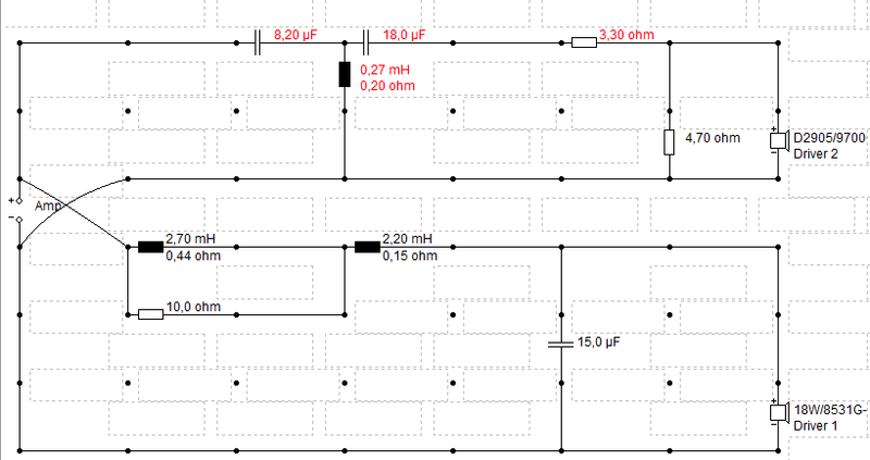
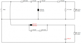
schematic filter 05

serial resistance coil 0.82m/0.30E
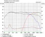
SPL and power response filter 05

The power responses are the lower curves.
The power response is a lot more flat with this filter compared to filter 04.
Horizontal 15 30 45 60 75 90 deg response normalized to 0 deg response

The horizontal off axis boost at 2500Hz is caused by the tweeter position too close to the top of the cabinet.
Later on we can try to attenuate the SPL at 2500Hz on axis.
Better to listen first to this filter.
As an information, the polar response of the tweeter in the cabinet. Responses are normalized to the on axis response.
Polar response tweeter in enclosure
1.28 - 2.56 - 3.84 - 6.4 - 12 kHz

This is not so good and completely caused by the tweeter position on the front baffle. And of course this cannot be solved by the X-over filter.
To avoid these kind of problems, Leap is a very interesting tool to simulate these responses before starting to built.
There are some problems with this speaker setup. Especially the tweeter is positioned to close to the top, with a serious impact on the horizontal off axis response, that could be better.
These are the responses.
schematic filter 05
serial resistance coil 0.82m/0.30E
SPL and power response filter 05
The power responses are the lower curves.
The power response is a lot more flat with this filter compared to filter 04.
Horizontal 15 30 45 60 75 90 deg response normalized to 0 deg response
The horizontal off axis boost at 2500Hz is caused by the tweeter position too close to the top of the cabinet.
Later on we can try to attenuate the SPL at 2500Hz on axis.
Better to listen first to this filter.
As an information, the polar response of the tweeter in the cabinet. Responses are normalized to the on axis response.
Polar response tweeter in enclosure
1.28 - 2.56 - 3.84 - 6.4 - 12 kHz
This is not so good and completely caused by the tweeter position on the front baffle. And of course this cannot be solved by the X-over filter.
To avoid these kind of problems, Leap is a very interesting tool to simulate these responses before starting to built.
Last edited:
thanks.
the tweeter is 9.5cm from the top and 8.5 from the side.
Thank you very much, now i can't try it because I don't have a 0.82mH inductor.
the tweeter is 9.5cm from the top and 8.5 from the side.
Thank you very much, now i can't try it because I don't have a 0.82mH inductor.
Ok paul, very claryfing
But i am a little confused. Where I can learn more about the meaning of SPL, power response (acoustic response) and the differences between them? On axis and off axis response why are they so important and how work with them?
Anyway, I will try your xover 03 and wait for your genial idea to finish the filter 🙂
Regards
Cucicu,
I will post a short explanation of these items later. Then you will have already some understanding.
This is also a very interesting well known presentation by Floyd Toole.
https://www.youtube.com/watch?v=zrpUDuUtxPM
Ok.
I think this speaker will never sound as good i was expecting.
I have a brand new mid driver 12M 4631g00, maybe i could go for the ekta by troels gravesen...
I listened to it at a friends home but i dont like it very much.
If I dont ask much, paul could you please make a simulation of it for me? I think it could be a very good design but xover needs to be adjusted.
If you can do it for me, here is the page
EKTA
Tweeter is d2905/9700 and baffle is right square (no chamferings and the speaker is not tilted back).
Many thanks Paul!
Maybe this should be good?
This is the response, filter 06. It is a good one to try out. It will give you an indication if a flat SPL sounds good with this speaker.
Almost the same response as filter 03.
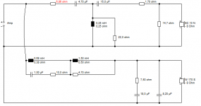
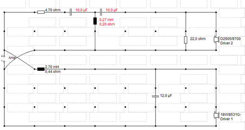
Schematic filter 06

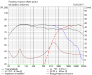
SPL and power response filter 06

I'm just eating popcorn on the sideline here. But I have been doing a bit of delving too. 🙂
I got interested in that Michael Chua passive bafflestep design, that you seem to have taken on board.
It's actually pure BBC. This is the LS5/9, documented superbly by Mark Hennessy:
Rogers Loudspeakers › LS5/9
And BBC style still has strengths. Graham Audio still make the LS5/9:
Journeys in Audio Subjectivism ? Part Five - Positive Feedback
I discovered a lot about it, and why it is good. But it didn't directly solve the problem here, which seems to be a +2dB 500Hz presence in the tower cabinet by Troels. The better idea might be to invert the drivers, as John DeVore does. But I like the BBC filter enough to try it soon. Of course, some details change with the Scanspeak drivers. I was using something else.
Attachments
im gonna try Paul xover 06.
But I am a hard head, and cant' explain why zaph zrt tower (same 22,5cm baffle) sounds good without any baffle step compensation (having also a major sensitivity, around 85db).
so I tried to simulate a symmetric LR4 (zaph's one) for "poor" baffles. and, with Paul's help, here we are:
But I am a hard head, and cant' explain why zaph zrt tower (same 22,5cm baffle) sounds good without any baffle step compensation (having also a major sensitivity, around 85db).
so I tried to simulate a symmetric LR4 (zaph's one) for "poor" baffles. and, with Paul's help, here we are:
from zaph site:
Actual measured response is very close to the modeled with the biggest difference being in the 400-500 Hz range. Seeing as the impedance curve with the crossover in place is exactly the same as the modeled curve, this is likely due to a mild difference between the individual driver measurements used in the model, and the system response curve. The model uses on-axis data with piston based off-axis simulation for a given mic location, while the actual measured system response is real. The mic location for the woofer response used in the model is 6" lower that the mic location used in the measured system response. Some floor bounce still comes through a bit in the nearfield woofer plots with diffraction added. This floor bounce is at a mildly different frequency and level for the measured system response compared to the driver curves taken for modeling, and the difference presents itself in the 400-500 Hz range. This is more than anyone wants to know, but I like to have a perfect grasp on differences between modeled and measured - even if it's only 1dB.
Measured frequency response on-axis, 10ms window

where is the 500-1000hz bump??
Actual measured response is very close to the modeled with the biggest difference being in the 400-500 Hz range. Seeing as the impedance curve with the crossover in place is exactly the same as the modeled curve, this is likely due to a mild difference between the individual driver measurements used in the model, and the system response curve. The model uses on-axis data with piston based off-axis simulation for a given mic location, while the actual measured system response is real. The mic location for the woofer response used in the model is 6" lower that the mic location used in the measured system response. Some floor bounce still comes through a bit in the nearfield woofer plots with diffraction added. This floor bounce is at a mildly different frequency and level for the measured system response compared to the driver curves taken for modeling, and the difference presents itself in the 400-500 Hz range. This is more than anyone wants to know, but I like to have a perfect grasp on differences between modeled and measured - even if it's only 1dB.
Measured frequency response on-axis, 10ms window
where is the 500-1000hz bump??
Cucicu, I didn't come here for an argument. You get nowhere with that.
You said you had a tonal problem with your speaker. There are many ways to filter a speaker. There are many cabinet designs.
But what I have found here, is that a bookshelf on stands has a different response from Troels' or Zaph's tower design. Only 2dB at 500Hz, but that would be a lot on tweeter level.
Zaph's design is where he takes a different approach to Troels. Taking crossover down too low causes as many problems as it solves, IMO. I think he's missed a trick by not applying a notch too.
But if you think Zaph is not applying bafflestep, you are dreaming. But really, it's your speaker, your project. I just play with ideas. And I've given you loads.
Attachments
I wasn't searching for an argument too. Sorry for that impression.
I thank you all for your feeback.
I only wanted to say that zaph project has the same characteristic of mine, same baffle wideness and same mid bass driver used. So I can't understand why his project is ok at the measures he made (img above you can see there's no bump) and not mine.
regards
I thank you all for your feeback.
I only wanted to say that zaph project has the same characteristic of mine, same baffle wideness and same mid bass driver used. So I can't understand why his project is ok at the measures he made (img above you can see there's no bump) and not mine.
regards
im gonna try Paul xover 06.
But I am a hard head, and cant' explain why zaph zrt tower (same 22,5cm baffle) sounds good without any baffle step compensation (having also a major sensitivity, around 85db).
so I tried to simulate a symmetric LR4 (zaph's one) for "poor" baffles. and, with Paul's help, here we are:
Paul, could you simulate this?
I'm listening to it now and it's very neutral an natural, non audible bump on 500-1000hz. don't ask me why 🙂 but I'm very happy for this.
I only would need an help on the tweeter section, as the mid-high frequencies are little back, I think starting from 3khz....voices are backward. it needs some brilliance more.
thanks
thanks.
the tweeter is 9.5cm from the top and 8.5 from the side.
Thank you very much, now i can't try it because I don't have a 0.82mH inductor.
That is the tweeter center position? That is not in the middle of the front baffle. I have placed the tweeter in the middle of the baffle.
That gives an SPL difference, a different SPL ripple. Probably there is no change needed for filter. I will change in my simulation.
Paul, could you simulate this?
I'm listening to it now and it's very neutral an natural, non audible bump on 500-1000hz. don't ask me why 🙂 but I'm very happy for this.
I only would need an help on the tweeter section, as the mid-high frequencies are little back, I think starting from 3khz....voices are backward. it needs some brilliance more.
thanks
Here are the results of filter 07 🙂
schematic filter 07

C15 changed to 12uF
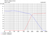
SPL and power filter 07

C15=12uF
Cucicu, maybe listen also to filter 06, which is more flat for low frequencies. In the case your drivers are conform the specification.
It is a pity you cannot measure. Now you don't have any reference of the absolute SPL of your speaker.
Concerning the published Zaph SPL curve. When you observe that curve, you can see there is a splice at 450Hz. In this way you can camouflage the boost very nicely. It means that the low fequency part of the curve is not correct, that level is too high.
I agree with Steve on this point, you cannot make the SPL flat without the baffle boost compensation in the filter.
This doesn't mean that the Zaph speaker doesn't sound well, but its SPL is not flat down to below 100Hz.
Last edited:
- Home
- Loudspeakers
- Multi-Way
- Scan-Speak crossover help