Well, if there is a bump in this region, it may be originating from the air resonance of the inner height of the cabinet. All else being ok as you say, this should be the issue.
I measured the impedance and there areno peaks in that region. If it would be a resonance in that range I shoul see an impedance peak, isnt it?
Ok.
But i wouldnt go for the series crossover cause it seem a bit confused..
Can you recommend a parallel filter or a frequency for crossing the driver? best to cross them high (2.5khz-3khz) or low (1.5khz-2khz)?
Due to beaming I wouldn`t consider a crossover higher than 2Khz.
Hi guys,
Interesting topic. I also have done a simulation of this speaker in Leap, free space in enclosure. And designed a crossover.
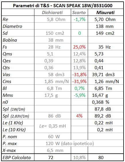
I have the taken the specification data of the drivers for the simulation.
I get the following results.
Unfiltered SPL's of drivers:

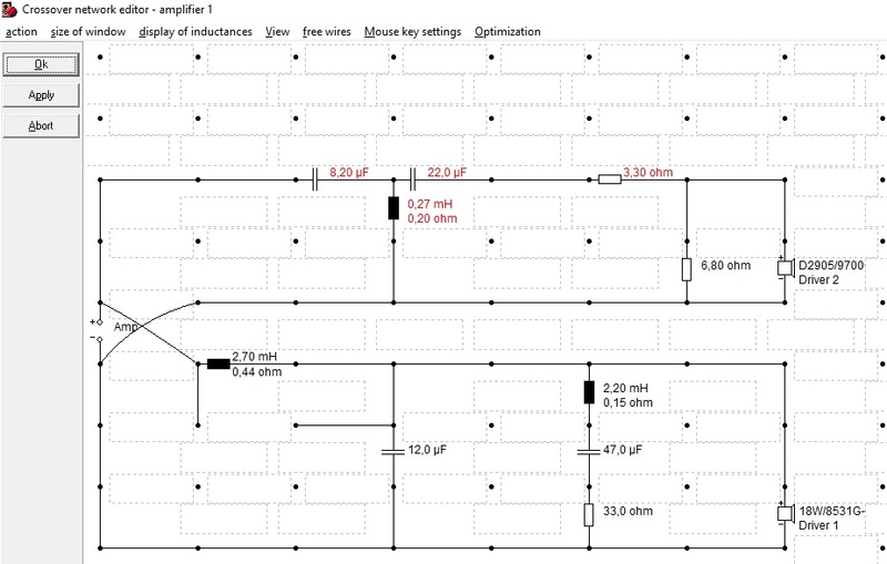
X-over schematic

Serial resistances coils:
woofer: 3.9m/0.65E ; 1.5m/0.38E ; 1.2m/0.34E
tweeter: 0.39m/0.2E
Filtered SPL's @ my filter

To compare with I have also simulated the X-over posted by Lojzek using my SPL Leap responses of the drivers.
Filtered SPL's @ Lojzek posted filter

There is a difference comparing this SPL with the SPL posted by Lojzek with the same filter (Zaph filter).
The unfiltered SPL's seem to be different.
The baffelstep response around 800Hz is not the same.
At 100Hz I simulate a SPL of about 81dB and it is about 83.5dB in Lojzek's posted SPL.
The infinite baffle respons of the Scanspeak 18W8531 is about 87dB at 100Hz.
In an enclosure in free space it will be 6dB down due to the bafflestep, that is 81dB.
Hope this simulation can help a little to solve the problem.
Interesting topic. I also have done a simulation of this speaker in Leap, free space in enclosure. And designed a crossover.
I have the taken the specification data of the drivers for the simulation.
I get the following results.
Unfiltered SPL's of drivers:
X-over schematic
Serial resistances coils:
woofer: 3.9m/0.65E ; 1.5m/0.38E ; 1.2m/0.34E
tweeter: 0.39m/0.2E
Filtered SPL's @ my filter
To compare with I have also simulated the X-over posted by Lojzek using my SPL Leap responses of the drivers.
Filtered SPL's @ Lojzek posted filter
There is a difference comparing this SPL with the SPL posted by Lojzek with the same filter (Zaph filter).
The unfiltered SPL's seem to be different.
The baffelstep response around 800Hz is not the same.
At 100Hz I simulate a SPL of about 81dB and it is about 83.5dB in Lojzek's posted SPL.
The infinite baffle respons of the Scanspeak 18W8531 is about 87dB at 100Hz.
In an enclosure in free space it will be 6dB down due to the bafflestep, that is 81dB.
Hope this simulation can help a little to solve the problem.

Many thanks! I see that bumps on 800hz.
How can make the xover for better results?
Don't you have the components to try out the X-over I have posted?
If not, I can try to make a redesign based on your current crossover?
You are playing now with the filter that Lojzek posted, when I understand well.
This is a X-over design with minor changes w.r.t. your current filter.
Maybe you can try out this one ?
Schematic

coil resistances
woofer 3.9m/0.65E ; 0.68m/0.25E
filtered SPL

Maybe you can try out this one ?
Schematic
coil resistances
woofer 3.9m/0.65E ; 0.68m/0.25E
filtered SPL
Cucici,
Like Lojzek is mentioning also, maybe you should try to do some measurements. My simulations are based now on the driver specifcations, which can be different of those you have.
SPL at 1m and 2.83Vrms in your room of both unfiltered woofer and tweeter at a heigth between the two drivers.
Same position for both to see relative SPL differences between the drivers.
And the impedances at about 1Vrms of the unfiltered drivers in the enclosure. Correct woofer impedance peak values are needed for a correct X-over design. Now I do some assumptions in the simulation.
The infinite baffle respons of the Scanspeak 18W8531 is about 87dB at 100Hz.In an enclosure in free space it will be 6dB down due to the bafflestep, that is 81dB.Hope this simulation can help a little to solve the problem.
Hi Paul, the free space spl discrepancy stems from the spl where I have spliced the box response to traced Zaph measurement. I've done it where these appeared better alligned. Unibox and Woofer Box and Circuit Designer calculate SPL/2,83V/1m to higher values than official SS data.
yes Paul you're right, I don't have all the components...
I miss the 3.9mH coil...I have 2.7mH and 2.2mH.
anyway I can't measure, the microphone is too bad....would be an unuseful job...
if can help, this xover I'm trying is the best right now, but there is yet too mid/bass and high frequencies are a little back.....but I have eliminated the paper sound!!!! can you simulate this? if you help me with this I think we are on the go.....It would need more light and more transparency from the tweeter but not more mids from it! thank you at all
Hi Paul, the free space spl discrepancy stems from the spl where I have spliced the box response to traced Zaph measurement. I've done it where these appeared better alligned. Unibox and Woofer Box and Circuit Designer calculate SPL/2,83V/1m to higher values than official SS data.
Hi Lojzek,
Box calculators like Unibox show infinite baffle responses and don't take into account the impact of the enclosure in free space for low frequencies. So I understand that in your SPL post, the SPL is higher for low frequencies.
What I don't understand well, is the SPL diiference at about 800Hz of a few dB.
At which frequency do you splice? And above the splice for higher frequencies the SPL is based on a measurement in enclosure?
if can help, this xover I'm trying is the best right now, but there is yet too mid/bass and high frequencies are a little back.....but I have eliminated the paper sound!!!! can you simulate this? if you help me with this I think we are on the go.....It would need more light and more transparency from the tweeter but not more mids from it! thank you at all
Good feedback. I will simulate. And I can do some little modification proposals also, that you can try out.
All is based on specification data, remember, but we can try it 🙂
Cucicu,
This is the response of your current filter, I call it "filter 01"
schematic filter 01

SPL filter 01 and LR4 targets at 2000Hz

I have added LR4 targets at 2000Hz in the plot.
You see that the tweeter is good on target with your filter.
The woofer response can be better, there is some boost.
I will have a further look at it.
Concerning my previous filter proposals there is an error in it.
The tweeter impedance was not correct. So, forget these previous proposals.
I make new ones.
This is the response of your current filter, I call it "filter 01"
schematic filter 01
SPL filter 01 and LR4 targets at 2000Hz
I have added LR4 targets at 2000Hz in the plot.
You see that the tweeter is good on target with your filter.
The woofer response can be better, there is some boost.
I will have a further look at it.
Concerning my previous filter proposals there is an error in it.
The tweeter impedance was not correct. So, forget these previous proposals.
I make new ones.
Hi Lojzek,
What I don't understand well, is the SPL diiference at about 800Hz of a few dB.
At which frequency do you splice? And above the splice for higher frequencies the SPL is based on a measurement in enclosure?
My measurement was based on Zaph's measurement and I did all the work in Response Modeler. There is a baffle model, box response model and box plot splicing section. After loading the infinite response measurement, I did the hard splicing of the box response(TSP) to this infinite response at 200 Hz with manual lowering of the box response SPL until I thought would be enough to meet the measurement. After that the baffle response curve was added to existing curve( infinite + box response). Had the phase calculated and that was it. Impedance was modeled as a 32 lit vented but I used the curve until 200 Hz and from there up the impedance plot of the official scan speak impedance in free air. That I did separately in a text editor.
Cucicu,
This is the response of your current filter, I call it "filter 01"
schematic filter 01
View attachment 602451
SPL filter 01 and LR4 targets at 2000Hz
View attachment 602452
I have added LR4 targets at 2000Hz in the plot.
You see that the tweeter is good on target with your filter.
The woofer response can be better, there is some boost.
I will have a further look at it.
Concerning my previous filter proposals there is an error in it.
The tweeter impedance was not correct. So, forget these previous proposals.
I make new ones.
ok, right now I have made some adjustements to filter01, could you try to work on this? it's very better than the other, very good but maybe it needs some adjustements
My measurement was based on Zaph's measurement and I did all the work in Response Modeler. There is a baffle model, box response model and box plot splicing section. After loading the infinite response measurement, I did the hard splicing of the box response(TSP) to this infinite response at 200 Hz with manual lowering of the box response SPL until I thought would be enough to meet the measurement. After that the baffle response curve was added to existing curve( infinite + box response). Had the phase calculated and that was it. Impedance was modeled as a 32 lit vented but I used the curve until 200 Hz and from there up the impedance plot of the official scan speak impedance in free air. That I did separately in a text editor.
your crossover is very similar on the simulator to mine. it's essentially correct and also phases are ok but the issue on listening is the 400-1000hz range which is up of a couple of db's but in the simulation we can't see that. do you know why? in the simulation it seems alligned but not in Paul's simulation
Hi Lojzek,My measurement was based on Zaph's measurement and I did all the work in Response Modeler. There is a baffle model, box response model and box plot splicing section. After loading the infinite response measurement, I did the hard splicing of the box response(TSP) to this infinite response at 200 Hz with manual lowering of the box response SPL until I thought would be enough to meet the measurement. After that the baffle response curve was added to existing curve( infinite + box response). Had the phase calculated and that was it. Impedance was modeled as a 32 lit vented but I used the curve until 200 Hz and from there up the impedance plot of the official scan speak impedance in free air. That I did separately in a text editor.
Maybe there are some doubts about the baffle response curve that you add.
The baffle response, does it boost above 0 dB around 800Hz?
It has to boost with this kind of enclosure.
Cucici,
I will simulate your last filter version.
Can you give me some coil values you have at home? For the case I make a filter proposal for test.
I will simulate your last filter version.
Can you give me some coil values you have at home? For the case I make a filter proposal for test.
- Home
- Loudspeakers
- Multi-Way
- Scan-Speak crossover help