I got myself a star quad for the headphone-connection... But:
Do I connect the shield as well as the inner pair to ground too?
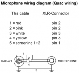
Or should I follow the SCM of the data sheet (although a balanced microphone connection)?
Do I connect the shield as well as the inner pair to ground too?
Or should I follow the SCM of the data sheet (although a balanced microphone connection)?
Attachments
You could use each wires pair as HP out & ground for each channel. Connect the shield's one end at the jack's common and trim its other end unconnected.
Thank you again!
Good I asked, I would have connected the shield at the other end… (like, connect the shield on the „lower“ end of the chain?)
🙂
Good I asked, I would have connected the shield at the other end… (like, connect the shield on the „lower“ end of the chain?)
🙂

Yeah, but this V1.03 board isn't already bridged for channel grounds. They are independent. Bridge point will happen at the HP jack's common ground pin and its easier to also refer the shield there.Thank you again!
Good I asked, I would have connected the shield at the other end… (like, connect the shield on the „lower“ end of the chain?)
🙂
I guess I will if there will (be hum) 😀
But those channel grounds—they‘re bridged by the i-select‘s topology/lay-out aren’t they?
But those channel grounds—they‘re bridged by the i-select‘s topology/lay-out aren’t they?
Yes, input side select does that. Some would go bridge at the volume pot even when using just a two inputs rocker switch. Or run a busbar through all RCAs. TRS jack classic headphones cable forces an output side channels ground bridge.
Still open policy in the main board is good not to lock you bridged if different ground schemes must be implemented.
Still open policy in the main board is good not to lock you bridged if different ground schemes must be implemented.
Hello
Is the wiring correct to test the PSU?
White wire (L) and black wire (N) from IEC to terminal block.
I think the beginning of the primaries and secondaries are in indicated with yellow and black tape respectively by the manufacturer.
Thank you in advance!

Is the wiring correct to test the PSU?
White wire (L) and black wire (N) from IEC to terminal block.
I think the beginning of the primaries and secondaries are in indicated with yellow and black tape respectively by the manufacturer.
Thank you in advance!
Thats on the secondaries blue/blue+black/blue yes? Then, yes.
I had to measure the correct polarity of the secondaries, as toroidy does not mark the winding‘s direction on the wires.
If the voltage is good, then it’s good. If not, it will show zero iirc…
I had to measure the correct polarity of the secondaries, as toroidy does not mark the winding‘s direction on the wires.
If the voltage is good, then it’s good. If not, it will show zero iirc…
Isn't there a published wires color guide by the transformers manufacturer? What is it, Toroidy?
Yes, Toroidy. Just found the mistake, the primaries are blue, the secondaries are white-white and black-black.
The marked white and black wires go then to ACs and the unmarked combined to CT?
Many thanks again!
The marked white and black wires go then to ACs and the unmarked combined to CT?
Many thanks again!
Its good to use a Variac or a dim bulb tester if you got. To safeguard against possible over current situations when testing.
- Home
- Source & Line
- Analog Line Level
- Salas DCG3 preamp (line & headphone)