Typical reasons would be the manufacturer states nominal AC output spec at full current load, there's higher mains than nominal at the region, some manufacturing tolerances contribution.
Maybe a little overshoot on the installation-side? (Salas knows muchmuchmore, but I’m in chatty mode 😇)
[edit: see?]
(Your next step will be to connect the psu, everything will be fine, and you just want to verify it outputs a little lower than 18V… then you will want to connect The DCG3, yay!)
[edit: see?]
(Your next step will be to connect the psu, everything will be fine, and you just want to verify it outputs a little lower than 18V… then you will want to connect The DCG3, yay!)

Its ok they are just good transformers with tight regulation (they don't lose much ac with moderate loading). Anyway you will see their final output when loaded with the DCG3's bias.
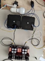
DC values are on both sides are 17.09 and 17.11.Its ok they are just good transformers with tight regulation (they don't lose much ac with moderate loading). Anyway you will see their final output when loaded with the DCG3's bias.
And the 100 Watt dim bulb tester did appears still intact.DC values are on both sides are 17.09 and 17.11.
Picture? When DCSTB will be loaded with DCG3 there will be more current in the transformers and you will check their AC level again.
Now the values are 17.04 on one side and 17.04/17.05 on the other side. Sorry, I am not good in taking pictures while measuring.Picture? When DCSTB will be loaded with DCG3 there will be some current in the transformers and you will check their AC level again.
Attachments
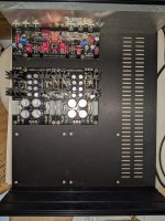
Its a clear picture. I see DCSTB sections perfectly lit and dim bulb perfectly dim. All well up to now and congratulations.
Now the values are 17.04 on one side and 17.04/17.05 on the other side. Sorry, I am not good in taking pictures while measuring.
Thank you Salas!Its a clear picture. I see DCSTB sections perfectly lit and dim bulb perfectly dim. All well up to now and congratulations.
Still have not soldered in the JFETs on the signal board, I guess this needs to be done before proceeding including mounting them on the heatsink.
Hello all
some incremental progress, some more questions:
some incremental progress, some more questions:
- The build guide states in the section 6: “Fuse the transformer(s) primary as rated by its manufacturer.“ Does this mean that the IEC also needs a fuse or just that the primaries need to be connected to a terminal block?
- In section 7 it says: “short the signal inputs and measure the DC offset across each line output.“ Not sure what this means/what I have to do.
- Grounding is still confusing to me: what I understand so far is that all the RCA inputs and output, selector switch/pot (no i selector board), headphone socket and signal board (v.1.03, any one input/output ground point) need to be connected to one common point of the chassis. I found some more information in post #3,684, but not sure I completely understand. Still have some CL60 thermistors from another project.
- Earth wire of the transformer just needs to be trimmed (ends wrapped in isolation tape) and does not need to be connected to chassis ground?
- Soldering the heat sinks of the PSU to the board is crucial?
- Would there be an advantage in using heat dissipation foil (still have some KERAFOL 86/82) in adddition to or instead of the silpads for mounting the MOSFETs to the heatsink?
Attachments
As these are recently done things by me, Ihope I can ease things a bit (and make Master Salas a bit relieved/relaxed 😇)
1) install a fused IEC
2)put a thick piece of wire through left and right in+ / in-gnd (separately of course), turn dcg3 on and measure DC-millivolts on the out +/ out-gnd. Turn the trimmer until it gets as close to 0 as possible.
3) connect everything you need to DCG (inputs to selector to volume-pot to DCG3-in. Connect DCG3 to ground through a cl60 od other ground-lifting tnings
Connect the transformers yellow-green wires to the chassis indepentantly (that is, NOT with DCG3‘s thermistor.
My star-ground is like this:
-Chassis
-IEC-ground
-transformer shields
-CL60s (1 per channel)
Its all on 1 screw, the IEC-gnd is secured with its own bolt.
4)Soldering the heatsinks to the boards relieves the parts from the HS‘s weight, so it surely is better practice.
5) use keratherm OR the mica+goop (keratherm is easyer for no goop required)
HTH
Many thanks!As these are recently done things by me, Ihope I can ease things a bit (and make Master Salas a bit relieved/relaxed 😇)
1) install a fused IEC
2)put a thick piece of wire through left and right in+ / in-gnd (separately of course), turn dcg3 on and measure DC-millivolts on the out +/ out-gnd. Turn the trimmer until it gets as close to 0 as possible.
3) connect everything you need to DCG (inputs to selector to volume-pot to DCG3-in. Connect DCG3 to ground through a cl60 od other ground-lifting tnings
Connect the transformers yellow-green wires to the chassis indepentantly (that is, NOT with DCG3‘s thermistor.
My star-ground is like this:
-Chassis
-IEC-ground
-transformer shields
-CL60s (1 per channel)
Its all on 1 screw, the IEC-gnd is secured with its own bolt.
4)Soldering the heatsinks to the boards relieves the parts from the HS‘s weight, so it surely is better practice.
5) use keratherm OR the mica+goop (keratherm is easyer for no goop required)
HTH
Okay, a fused IEC is crucial and I will need 2 separate ground/earth posts.
Now I understand how measurement is done: your post #6,485 depicts how measurement is done.
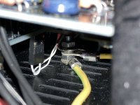
Do you also have photo showing the grounding?
Thanks again!
For dual 50VA transformers put 1.25A slow blow fuse in the IEC if in 230V mains countries or 2.5A if in 115V mains countries. To withstand the inrush current at power on. That's safe enough, no further individual primary side fuses will be needed.1) install a fused IEC
Here ya go, although there’s not much discernible 🙃photo showing the grounding
The CL60s aren visible because they‘re wrapped in black shrinktube and without a spade. They‘re above the yellow wires (which doesn‘t matter as long as the trannies aren’t („electronically“) behind the CL60.
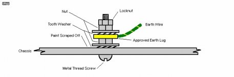
If still in doubt, look after sound-au safety-ground or similar, I believe he has a very clear drawing of how it should be done. (Maybe Salas or some other good soul has a link/pic at hand…)
Attachments
Thank you!
I have a Schurter 4304.6090 IEC Power Entry Module. This has 2 fuse holders already wired in, one for L and one for N.
Can this be used in a 230 V environment for this amp, and if so at what fuse/amperage rating?
I have a Schurter 4304.6090 IEC Power Entry Module. This has 2 fuse holders already wired in, one for L and one for N.
Can this be used in a 230 V environment for this amp, and if so at what fuse/amperage rating?
look at salas' answer, above.
(Although these double-fused IEC have been hotly discussed here, so hot that I decided not to use them...)
BTW, here's that image and its long article...
(Although these double-fused IEC have been hotly discussed here, so hot that I decided not to use them...)
BTW, here's that image and its long article...
Attachments
- Home
- Source & Line
- Analog Line Level
- Salas DCG3 preamp (line & headphone)