Those double fused IEC are controversial. If only the neutral fuse blows, the circuit fails live.
Meaning a higher chance of damaged components with this scenario?Those double fused IEC are controversial. If the neutral fuse blows, the circuit fails live.
I guess the chance of a blown neutral fuse is not higher than that of a blown L fuse.
You rather would recommend to opt for a single fuse IEC?
I am not an electrician I don't know the regulations details. Especially in each different country. I suppose double fused is for places where the plug can be reversed in the socket. Should not be a problem if its not prohibited in your country.
Meaning more of a chance to fool service persons for gear or a buildingMeaning a higher chance of damaged components with this scenario?
Meaning more of a chance to fool service persons for gear or a building
Compliance to Safety Standards is no joke, and as builders of custom equipment that will not have the benefit of being reviewed by a safety certification body, we owe it to ourselves, our families and our neighbors to build equipment that would be found in compliance if reviewed and tested.
The double fuse may be of benefit if Line and Neutral reversal is possible or likely, but its proper application is not as simple as just adding a second fuse. If I recall properly, it is required that if the Neutral fuse opens because of a fault, then both fuses must open. It's unlikely any DIY builders will apply "faults" to their equipment to verify this result. Not that applying shorts to the AC line stages and the transformers and rectifiers of equipment isn't exciting, but most of us probably won't go there.
I think a better approach would be to test that the outlets where we are going to plug in our custom equipment are correctly wired (a good idea anyway), and use a single fuse in the Line (hot) circuit of our equipment along with an IEC inlet that does not allow for plug reversal.

Thank you for advocating your point of view. As this is far beyond my knowledge of the field I think it is prudent to opt for a single fuse IEC socket.Compliance to Safety Standards is no joke, and as builders of custom equipment that will not have the benefit of being reviewed by a safety certification body, we owe it to ourselves, our families and our neighbors to build equipment that would be found in compliance if reviewed and tested.
The double fuse may be of benefit if Line and Neutral reversal is possible or likely, but its proper application is not as simple as just adding a second fuse. If I recall properly, it is required that if the Neutral fuse opens because of a fault, then both fuses must open. It's unlikely any DIY builders will apply "faults" to their equipment to verify this result. Not that applying shorts to the AC line stages and the transformers and rectifiers of equipment isn't exciting, but most of us probably won't go there.
I think a better approach would be to test that the outlets where we are going to plug in our custom equipment are correctly wired (a good idea anyway), and use a single fuse in the Line (hot) circuit of our equipment along with an IEC inlet that does not allow for plug reversal.
Alright, the results are in (and a single fuse (L) IEC is in place):
Channel 1:
+/- 16.93 VDC measured on the signal board.
1.24 VDC across R10.
Line output:
alternating between 0.2mV and -0.5mV.
HP output:
alternating between 0.2mV and -0.4mV.
Channel 2:
+/- 16.91 VDC measured on the signal board.
1.26 VDC across R10.
Line output:
alternating between 0.5mV and -0.1mV.
HP output:
alternating between -0.8mV and -0.16mV.
.
Are these values sufficient or should I try to tweak further?
Is the discrepancy between Line and HP output (channel 2) of concern/pointing at a specific issue respectively?
As always many thanks in advance.
Hi, they are sufficiently reassuring. Only extra thing between line and HP output is R15. Your little different mV offset indications should be random.
Thank you Salas!
Unfortunately, I realised that, after a second verification, the mentioned output values were incorrect. The readouts should have been/are:
Channel 1:
Line output:
alternating between 2mV and -5mV.
HP output:
alternating between 2mV and -4mV.
Channel 2:
Line output:
alternating between 5mV and -1mV.
HP output:
alternating between -8mV and -16mV.
Are these values (without servo opamp in place) outside of acceptable limits?
Thank you again for your input and continued support.
They don't look excessive. Not out of place. Its about thermals and/or some noise. Also how different DMMs respond. The offset play could also change a bit if the line inputs are shorted or not. When there's a volume pot already installed it will short them at minimum position. Else it takes shorting links.
Thanks Salas! So far no volume pot connected. If I do not shorten input of channel 2 the readout for line and HP appears to be similar, ~50mV.They don't look excessive. Not out of place. Its about thermals and/or some noise. Also how different DMMs respond. The offset play could also change a bit if the line inputs are shorted or not. When there's a volume pot already installed it will short them at minimum position. Else it takes shorting links.
Try trim offset minimal before shorting the inputs then check where it goes when shorted. Maybe you could improve the offset a bit more or not by doing that.
The difference between line and HP output of about 16mV remains before and after shorting this channel about the same. Remaining channel does not appear to be affected whether shorted or not.Try trim offset minimal before shorting the inputs then check where it goes when shorted. Maybe you could improve the offset a bit more or not by doing that.
Still nowhere near alarming like a Volt DC and stubborn. After your best figures of "raw circuit" offset have been achieved its time to see what inserting the servo op-amps will do about it.
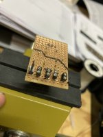
I may have found the reason for this asymmetry: there was almost a solder joint fusion between R15 and the adjacent leg of Q2. Also was cleaning up the board with F-02 spray afterwards. Now I could dial in channel 2 without this 16mV difference between line and HP output. Will monitor this for a bit longer before installing the servo op-amp.Still nowhere near alarming like a Volt DC and stubborn. After your best figures of "raw circuit" offset have been achieved its time to see what inserting the servo op-amps will do about it.
Last edited:
Thank you for pointing me in that direction in your post # 6,551.Good job spotting that detail.
Sorry, I meant Qa not Q2.
- Home
- Source & Line
- Analog Line Level
- Salas DCG3 preamp (line & headphone)