Solder-blob on 2 legs @ M1 (G+D, left + center)
Is there a chance it survived my gaffe?
Measured R, results are unconsistent across M1 - M4, so unless you recommend something else I will reconnect it and see what happens.
Since the board is off the sink, I recleaned it with IPA and have redone the keratherm-pads. I‘ll leave it for today to let it dry.
Good morning!
I have good news: channel two seems to be working, bias is down to around 1mV (immediately after powering it on, it is moving in slow waves from 10mV down to 0mV).
[Edit: voltage across R10 (10r) is 1.34V]
Should any further tests be done?
I must go and do some dayjob, unfortunately, so won’t be able to give it an ear until tomorrow or so!
Attachments
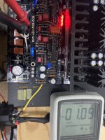
By bias mV you mean output DC offset without the servo op-amp in yet I believe. Yes it looks normal. Also 134mA output stage bias current is normal (1.34V/10Ω).
The pdf instructions set up steps will suffice for tests. Does not look it has a special issue after you spotted and removed the solder blob short from the M1 Mosfet.
The pdf instructions set up steps will suffice for tests. Does not look it has a special issue after you spotted and removed the solder blob short from the M1 Mosfet.
Good evening Tom
Although you can use „any“ other suitable PSU, the DCSTB is highly recommended.
Look after tea-bag‘s shop: https://reverb.com/shop/teabags-boutique
Be careful, most of it is highly tempting!
Although you can use „any“ other suitable PSU, the DCSTB is highly recommended.
Look after tea-bag‘s shop: https://reverb.com/shop/teabags-boutique
Be careful, most of it is highly tempting!
Last edited:
Thanks, it is temping .. this save me a lot of timeGood evening Tom
Although you can use „any“ other suitable PSU, the DCSTB is highly recommended.
Look after tea-bag‘s shop: https://reverb.com/shop/teabags-boutique
Be careful, most of it is highly tempting!
") .. now I have to make sure I order the right items
.. now I have to make sure I order the right itemsConductivity around the MOSFETs is touchy. Too tight, I got shorts when measuring. Slightly loosened, problem went away. Test first, then go. Mine measured fine, but then before fire up, "I made sure they were tight" and this shorted them, so when I fired up, problems.Thank you, Salas and cyberpup!
The 17.02vdc is on the output (line/G, with input shorted)…
It’s the channel that has the i-select stealing power from DCSTB btw. can‘t imagine this is the problem, as i-select is working and DCG3 turns on and measures correcly 17.3 vdc on the V+/GND and V-/GND.
Power wiring was correct (I color-coded the wires + verified with multimeter)
Since I was quite carefully during the build, and verified everything on scm and dmm, I am confident that at least the valuss on the resistors are correct—so I firstly will re-verify visually…
Same for the Mosfets, I took great care to have a good, plane, burr-free surface 😇, and I used the plastic-washers. Will of course recheck for nonconductivity!
I had to leave the workshop, so will make further measurements tomorrow.
Still, maybe these descriptions point to something specific?
Thanks again!
David
Russellc
Ah, those are the bad moments.
I seem to have been lucky though, it seems the DCG3 is behaving as supposed.
(One channel's offset is behaving funny, though, but I can't judge wether it's fine or not: it goes up and down ~10mV in, like, 10-15 seconds-cycles, after some 15 minutes or so, I believe it calmed down a bit? I will let it run some 30' and look after that, and then will be the great moment: In goes Opamp, first listening!)
Not sure about the headphone‘s wire. It will have to pass close to the psu as the connector will be placed on the frontplate…
Mogami 2520 or should it be beefier, like Mogami 2893?
https://www.cma.audio/detail/index/sArticle/1832
https://www.cma.audio/detail/index/sArticle/148
Mogami 2520 or should it be beefier, like Mogami 2893?
https://www.cma.audio/detail/index/sArticle/1832
https://www.cma.audio/detail/index/sArticle/148
If you haven't installed the 8 legged device, that may be normal, Salas can confirm...Ah, those are the bad moments.
I seem to have been lucky though, it seems the DCG3 is behaving as supposed.
(One channel's offset is behaving funny, though, but I can't judge wether it's fine or not: it goes up and down ~10mV in, like, 10-15 seconds-cycles, after some 15 minutes or so, I believe it calmed down a bit? I will let it run some 30' and look after that, and then will be the great moment: In goes Opamp, first listening!)
Russellc
Its not critical. Maybe choose the Neglex Quad.Not sure about the headphone‘s wire. It will have to pass close to the psu as the connector will be placed on the frontplate…
Mogami 2520 or should it be beefier, like Mogami 2893?
This is a good namethe always been good channel.
- Home
- Source & Line
- Analog Line Level
- Salas DCG3 preamp (line & headphone)