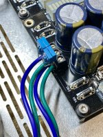
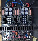
The diodes don't interfere since the DCin connector on the I-Select is located after them just at the 7812 reg chip's input.
In some cases it can lead to complicated issuesok I see. (I have to admit that did the "2-bridges-bungle" before, in my WLS18... Never heard anything not good so I did not realize it's not proper.)
I think i‘ve got (although not through the whole thread, but
» 'Separate' PSUs driven from one secondary is about the hardest way to do it. «
is more than a hint…
Many thanks, Salas!
Good night for now
» 'Separate' PSUs driven from one secondary is about the hardest way to do it. «
is more than a hint…
Many thanks, Salas!
Good night for now
One step at a time (although sometimes it's a backward step)
The i-select connection hasn't yet worked. I connected it from C1 (or C2), output measured a little above 25VDC, but i-select did not engage (no LED, no relay-click). I'll try to get it running from AC and see what this gives...
Another step though: Should I use a quasimodo-measured snubber-network, and is this the correct layout/location for it? (see attachment)
Many thanks
You attached the 25V raw DC feed to the in-selector's DCin connector and its LED did not light? The LED is driven by the 7812's output. Meaning a 12V DC regulated rail is present. Check voltages. Make sure you feed a positive polarity 25V raw DC to it.
Applying Quasimodo transformer secondary de-ringing network is up to you. If you got the test hardware. The DCSTB + DCG3 standard goes nicely even without it.
Thank you Salas.You attached the 25V raw DC feed to the in-selector's DCin connector and its LED did not light? The LED is driven by the 7812's output. Meaning a 12V DC regulated rail is present. Check voltages. Make sure you feed a positive polarity 25V raw DC to it.
Yes, that's how I did. Went on to test I-select on a Tx's 18V secondary (AC in), and this doesn't work either. Something's wrong with it, grr.
It was the easiest glitch aside forgetting to power it on: LED wrong way. Now it's lit, I-select CD output 12.1 VDC. 🙂
Sorry for bugging you all the time.
I am not understanding the statement "'Separate' PSUs driven from one secondary is about the hardest way to do it". Are you refering to creating +/- rails from a single winding, or connecting two bridge rectifiers (and capacitors and regulators) to a single transformer with a center tapped or dual secondaries? I believe the latter is perfectly acceptable.
😊It was the easiest glitch aside forgetting to power it on: LED wrong way. Now it's lit, I-select CD output 12.1 VDC. 🙂
Hi CyberpupI am not understanding the statement "'Separate' PSUs driven from one secondary is about the hardest way to do it". Are you refering to creating +/- rails from a single winding, or connecting two bridge rectifiers (and capacitors and regulators) to a single transformer with a center tapped or dual secondaries? I believe the latter is perfectly acceptable.
I was going to connect both the dcstb (PSU) and the i-select (with its own little PSU) to a secondary. Salas kindly pointed me to a discussion about the problems that could occur when doing so (where this quote comes from) …
The thread ( https://www.diyaudio.com/community/threads/single-transformer-multiple-bridges.205949/ ) is quite clarifying and recommendable. (I haven’t understood everything but still!
Well, I probably wouldn‘t have done so anyway because the DCSTB wants a centertapped connection, like
sec1 — sec1+sec2 — sec2
while i-select wants a mere +/0 DC.
Myleftear,
Thankyou for the link to the multiple bridge discussion. It is clear that multiple full-wave bridges connected to a single common winding results in placing diodes in parallel when the "-" output of the bridges are connected together at ground.
With respect to adding a bridge rectifier to the center-tapped circuit needed for +/- rails, it appears to result in a short. LTspice is nice in this regards as there is no actual smoke.
Cheers
Post #4933 has quasimodo implementation ideas. It's really hard to A/B but I like making stuff and it's good learning. (I didn't see an attachment on your post...)Another step though: Should I use a quasimodo-measured snubber-network, and is this the correct layout/location for it? (see attachment)

Last edited:
Ha, the honour goes to Salas alone, as he provided me/us that link... 🙂Thankyou for the link
Same here, it's all about making! (I'm confident I wouldn't hear a difference, and still, if it makes the Tx not ring, it's good. (yes it may be exaggerated but only a little, with 3 tiny parts)... Thank you for the hint to #4933 😉 , a beautiful implementation which I already copied twice (Old Soul, Wayne's BA18 LS), and was to copy again here. I didn't post images as I was in agony and cold sweat about the correct quasimodo configuration. (BTW, re:quasimodo, I felt a little overwhelmed with the CT, is it really 1 wire on one input, the other 3 on the others?)Post #4933 has quasimodo implementation ideas. It's really hard to A/B but I like making stuff and it's good learning. (I didn't see an attachment on your post...

Dear Salas
I oh so slowly got there:
Channel 1: 17.25VDC / -17.23VDC
Channel 2: 17.35 VDC / -17.33VDC
Temperature of the mosfets is below 40°C after 10 minutes or so…
Makes me feel good and confident.
Biasing etc must again wait (or I‘d be finished too fast)
I oh so slowly got there:
Channel 1: 17.25VDC / -17.23VDC
Channel 2: 17.35 VDC / -17.33VDC
Temperature of the mosfets is below 40°C after 10 minutes or so…
Makes me feel good and confident.
Biasing etc must again wait (or I‘d be finished too fast)
Attachments
Good morning!
So I stole an hour and got back to continue measurements.
Voltage drops across R10 (10r) is ~1.34V = 0.13A
Bias on one channel is down to +-1mV
Bias on other channel, well, ahem. I measure 17.02V DC! Something is bad, unfortunately.
Salas, can you please point me to where to put my nose?


So I stole an hour and got back to continue measurements.
Voltage drops across R10 (10r) is ~1.34V = 0.13A
Bias on one channel is down to +-1mV
Bias on other channel, well, ahem. I measure 17.02V DC! Something is bad, unfortunately.
Salas, can you please point me to where to put my nose?


Between which points you measure that 17.02V figure?. Confirm power wiring and Mosfets isolation on the questionable channel. No TO-220 tab should beep continuity to the sink where its not anodized.
Next, compare Vgs voltages (pin 1,3) for M3s.
Next, compare Vgs voltages (pin 1,3) for M3s.
Let me humbly suggest that the most likely problem with a newly built board is that an improper component has been installed, and the most likely candidate is a resistor value. An ohm meter is your best bet. Check across each resistor. Because the components are now part of a complex circuit, the value may read lower than expected. You can compare channel to channel, and take readings from each node to ground. Most likely some difference will show up. Also, since this is a new build with components mounted on a heatsink, the isolation of each part to the heatsink must be verified. The tiniest burr can short the isolator pad.
Thank you, Salas and cyberpup!
The 17.02vdc is on the output (line/G, with input shorted)…
It’s the channel that has the i-select stealing power from DCSTB btw. can‘t imagine this is the problem, as i-select is working and DCG3 turns on and measures correcly 17.3 vdc on the V+/GND and V-/GND.
Power wiring was correct (I color-coded the wires + verified with multimeter)
Since I was quite carefully during the build, and verified everything on scm and dmm, I am confident that at least the valuss on the resistors are correct—so I firstly will re-verify visually…
Same for the Mosfets, I took great care to have a good, plane, burr-free surface 😇, and I used the plastic-washers. Will of course recheck for nonconductivity!
I had to leave the workshop, so will make further measurements tomorrow.
Still, maybe these descriptions point to something specific?
Thanks again!
David
- Home
- Source & Line
- Analog Line Level
- Salas DCG3 preamp (line & headphone)
