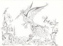
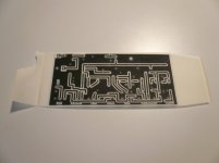
Imaginative. Reminds of medieval wall tapestry somehow. Is it a Colibri in a fantasy garden?
It does not matter where fed from, only remember they will light up sooner than the three (six in your doubled up two phases build) relay LEDs. Must use current limiting resistor in series to not burn them. Current/brightness will be (Vrail-1.8V)/Rled.
It does not matter where fed from, only remember they will light up sooner than the three (six in your doubled up two phases build) relay LEDs. Must use current limiting resistor in series to not burn them. Current/brightness will be (Vrail-1.8V)/Rled.
Will be nice to see it finished. As to how much extra leds current/glow and where to place them, you are the dcg3b show lighting director 🙂
Good to hear the Vishay ones are fine. Someday I will replace my stash of 20 year old International Rectifier versions with the Vishay.
Jim
As it wasn't specifically reported for IRF9610's case back then you may verify before replacing them. If you will bias it with simple means for common source on a breadboard and load its drain with say 150 Ohm you could measure its gain voltage output with 100Hz and 3kHZ input signal. If the 3kHz output is significantly lower, then it has the gfs kink. Same for any other IR original P-Type you may have and want to check with appropriate bias and loading for spot frequency gain test or sweep.
BTW in post#1 we can see flat THD in all graphs across bass and midrange so we suffer no possible weirdness in dcg3 as a whole
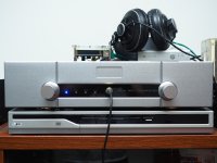
Add a laser engraved acrylic panel and input indicator in front of the chassis..Congratulations. First one here with a Muses chip-pot I believe. Let us know more about your system and how it blended in after you run it enough to grasp the qualities.
I use musese72320 chip-pot kit from Japan. As Salas mentioned, the pot circuit has it's problem. There are input caps and op-amps.
The input use the muse bp 22uf caps comes with kit. For the op-amp, I use the much cheaper muses8920 instead of the pricey moses01.
Here are my current equipment:
Spurce: Respbarry PI 3 + Schiit Modi 2 uber DAC.
Power Amp: VTL TT-25 Limited Edition tube power amp.
Speaker: Diaton PM-610MB 8ohm version.
Headphone: Superlux HD681D
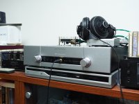
First thing I noticed is the detail. In some good live concert records, I can feel the atmosphere.As matter of the fact, I can definitely hear more information from all of my records.
The treble and bass are extended and fast in my system. Sound stage is good. I have to say that I love the sound of DCG-3. Thanks Salas and Tea fro the efforts so I can build one.
Next thing I would like to buy a pair of decent headphone.
Attachments

Next thing I would like to buy a pair of decent headphone.
In what price range?
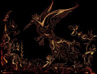
Thanks Salas! I just thought to play with an old sketch that seemed to be suitable to etch it on a PCB. It gives a very nice faint glow when DCG3 comes to life!
This is amazingly good work MagicBus...

How is you're procedure, when transfering some etch resistant foil or like to the bare pcb? -And how do you make it black afterwards 😕 🙂
Looking so good, as i am thinking of making a new topcover now 😀
Congrats.
Jesper.
In what price range?
I am thinking of something under USD$200.
Hi Jesper,This is amazingly good work MagicBus...
How is you're procedure, when transfering some etch resistant foil or like to the bare pcb? -And how do you make it black afterwards 😕 🙂
Looking so good, as i am thinking of making a new topcover now 😀
Congrats.
Jesper.
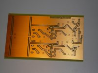
I use UV sensitive boards. I print the layout on transparent paper, just placing it on the PCB and expose it on a lamp - many youtube videos about that. After a little experimantation results can be amazing! The UV chemical can be left as copper protection mask while it allows soldering.
Attachments
I am thinking of something under USD$200.
For that price range the HD-598 probably. Has enough volume of clear mids for you used in full range point source speaker. HD-598 is not HD-600 / 650 fidelity territory yet but heading there.
Salas, the positive side of my PS decided to take a dump sometime today.
First thing I noticed was the LEDs on the negative side didn't illuminate.
Next I measured the + output voltage and it's 8.29V vs. 13.59V for the negative side.
I have 2 LEDs shorted out on each side and the transformer is a 25.2VCT unit.
The supply has worked flawlessly for about a month.
I haven't shorted anything out and the load on it was very light(only 3 op-amps).
Any idea what I should check/replace first?
Thank you.
Is that a custom DCSTB board for a custom application? Have you noticed high temperatures on its sinks or other components that may give a clue? What was the voltage drop across the supply (raw DC minus output DC) for the period it was working good?
Disconnect the load first. Check the rail voltages again. If still measuring bad the problem points to the supply only. Turn the power off and try to light up each LED in each bar one by one by means of DMM in diode mode probing at the sgments pins if your meter is capable. Test it on any red LED you may have around, or look up its diode mode voltage spec. If no more than 1.5V capable use a 9V battery with 1K resistor and two wires.
If you will find even one bad LED segment, replace the whole bar. In case the bars segments are all well in offline testing, turn the power on and take Vbe measurements for all transistors, also voltage drop measurements across all resistors, raw DC across each big capacitor, and list the results so we can start putting the failure's picture together.
Hi Salas,
After disconnecting the load on the positive side, all the LEDs in that segment mysteriously came back on. So I'm assuming the bar segment on that side is okay.
Also, the LEDs on the problematic positive side are now noticeably brighter than the negative side.
I took some voltage measurements as you suggested:
Voltages after the second 2200uF cap: -19V and 18.9V.
Across R1 .147V.
Across R2 .150V.
Across R3 .560V
Across R4 0V.
Across RxJ 15.9mV
Across RyJ 4.5mV
Does that help you at all?
Thanks.
Yes, helpful. Thanx.
Is RxJ = RyJ 1 Ohm standard start value? If yes the positive LEDS look like drawing >3x mA than the negative ones through a battered Q2. Normally they should be running ~4.5mA provided by J1 only as the normally bright ones do from J2. The RyJ drop follows R2 indicated mA, but RxJ shows much for what R1 indicates which is normal and close to R2's. Q1 Vbe OK, Q2 Vbe not, Q3 not, Q4 weird.
Replace Q2, Q3, Q4 and see what happens, Q2 & Q4 first, before connecting the load circuit. Its kinda weird to have had an erratic failure of BJTs on both polarity supplies. Are the MJEs non isolated and something grounded touched the sinks? Measure that the load isn't showing a short across its rails inputs to its ground also. Watch temperatures on sinks and on TO-92s. It might work by replacing the 550/560 but if finally having to desolder sink's legs for replacing Q3 too don't solder them back too soon. Let the MJE support the whole structure while investigating and fixing stuff in case some BJT blows again so to can rework faster. Good luck.
Hi Salas,
Yes, the Rx and Ry resistors are 1 ohm. In fact all resistor values are what's in your schematic.
The only thing I did was short 2 LEDs per side to get the voltage down to 13.8 or so.
The MJEs are not isolated from their heatsinks, but there's nothing else that touches or grounds out the heatsinks.
While the supply was working correctly, all components and heatsinks were stone cold.
I'm surprised by the failure of all these transistors, too. Especially since none have ever been overheated/stressed. I used name brand ON Semi for all the BJTs.
I'll replace the transistors you suggested and see what happens.
Q2 & Q4 are easy to go in a short. Even on a fast slip probing accident. They would carry too much current. Or on some static discharge, I can't say. We had no during normal service failure incidents with DCSTBs on DCG3s yet which run hot even, so no self failure mode sure knowledge to pass, especially on an unknown load circuit. Just investigate yours along the lines we discussed.
- Home
- Source & Line
- Analog Line Level
- Salas DCG3 preamp (line & headphone)