Nice to know Ricardo. Decided on which headphone to get too?
Now I got the Audeze LCD-3 ... nice finish and open sounding... 70 ohm... second hand deal
Yes.... it is subtle but the new opamp is more real sounding.
The spicy sound I experienced before is almost gone and I only changed the opamp... incredible.
I am now building the DCSTB and maybe that is what it needs to really sing. The V12R are maybe too incisive in this aplication.
PS: sent you an interesting e-mail
The spicy sound I experienced before is almost gone and I only changed the opamp... incredible.
I am now building the DCSTB and maybe that is what it needs to really sing. The V12R are maybe too incisive in this aplication.
PS: sent you an interesting e-mail
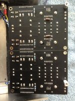
Broken diodes say that was a big prolonged short. Your Mosfets got assembled without Silpads if I remember well. Check various Vbe and other points like in Ammel's measurement list, because the few dark segmnets can be just signs of other problems yet unfixed than broken themselves. To verify the segments alone try light them up individually with a voltage source as he did. Don't forget to measure for shorts between the the +/0/- DCG3 inputs before attempting to use the supplies again after fixed. We don't know if your DCG3 passed fully undamaged yet.
P.S. Why we see no R1, R2 on the top DCSTB in your picture?
R1,R2 are on the bottom side.
Thanks for the responses. I followed your advice Ammel and checked the LEDs. The two inboard blocks each have a bar unlit, they measured .20 and .22ma, much lower than the others.
I also checked Vbe on the transistors. These ranged between .64V and .65Vbe for Q2, Q4 and .13V to .17V for J1, J2.
Resistors R1/R2 were .17-.18V and R3/R4 were .47V-.49V.
Rx/J and Ry/J = 1ohm
Output is -17.3V and +16.6V, and -16.9V and +17.3V
I’m hoping by changing the unlit LED blocks I’ll have a happy board.
Cheers
Keith
Attachments
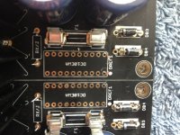
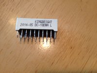
Unsoldering and replacing the Kingbrights doesn't look like it's going to be much fun.
Why don't you cut off the extra lead length of the MJE's instead of bending them over?
Looks like the 4 fuse clips in the center could use a little more solder on them.
Why don't you cut off the extra lead length of the MJE's instead of bending them over?
Looks like the 4 fuse clips in the center could use a little more solder on them.
Unsoldering and replacing the Kingbrights doesn't look like it's going to be much fun.
https://www.amazon.com/s/ref=nb_sb_noss_2?url=search-alias=tools&field-keywords=desoldering
R1,R2 are on the bottom side.
Thanks for the responses. I followed your advice Ammel and checked the LEDs. The two inboard blocks each have a bar unlit, they measured .20 and .22ma, much lower than the others.
I also checked Vbe on the transistors. These ranged between .64V and .65Vbe for Q2, Q4 and .13V to .17V for J1, J2.
Resistors R1/R2 were .17-.18V and R3/R4 were .47V-.49V.
Rx/J and Ry/J = 1ohm
Output is -17.3V and +16.6V, and -16.9V and +17.3V
I’m hoping by changing the unlit LED blocks I’ll have a happy board.
Cheers
Keith
R1,R2 (33R) are indicating about 5mA which is normal. So J1,J2 are working OK as CCS for the LEDs. They are JFETs so they present no Vbe, they just have a Vgs.
Vbe for Q2, Q4 BJTs reads normally. Across R3 and R4 there should be the MJE TO-220 transistors Vbe drops. Which seem rather low at 0.47-0.49V. Ammel's Q1 was 0.56V for instance (with no load at the output). I suspect they could be just passing the Rb1, Rb2 bleeders ~5mA load current through Q2,Q4 directly and the MJEs could be damaged. I hope not.
Please check the drop across RxJ and RyJ too so we see what current passes through the LED bars finally. They have weird failure modes, they usually fail open, but can fail emitting and still have some resistance too, still passing current.
Thanks.
Sometimes things go right. Replacing the LED bars was not the nightmare I expected. I wicked along the pins, inside and outside, gave the pins a very light wiggle and the bars dropped out. The pads are untouched. Eutectic solder. I celebrated with a beer.
The sinks are low warm. I hope the numbers below tell the story. If not, please let me know. With input to the right hand and the board face up, measurements read top to bottom.
Output:
-17.2V
+17.2V
+17.6V
-17.7V
Vdrop
RY/J .003V
Rx/J .005V
Rx/J .005V
RY/J .004V
R4 .50 V
R2 .13V
R1 .18V
R3 .48V
R3 .49V
R1 .19V
R2 .18V
R4 .50V
Vbe
.5
.6
.6
.5
Attachments
Thanks.
Sometimes things go right. Replacing the LED bars was not the nightmare I expected. I wicked along the pins, inside and outside, gave the pins a very light wiggle and the bars dropped out. The pads are untouched. Eutectic solder. I celebrated with a beer.
The sinks are low warm. I hope the numbers below tell the story. If not, please let me know. With input to the right hand and the board face up, measurements read top to bottom.
Output:
-17.2V
+17.2V
+17.6V
-17.7V
Vdrop
RY/J .003V
Rx/J .005V
Rx/J .005V
RY/J .004V
R4 .50 V
R2 .13V
R1 .18V
R3 .48V
R3 .49V
R1 .19V
R2 .18V
R4 .50V
Vbe
.5
.6
.6
.5
The voltages seem logical enough. Especially when you find some warmth on the sinks its a good sign. Do you have any 150-220 Ohm power resistor(s) or say 100 Ohm 2W for two in series = 200 Ohm 4W to load each polarity output heavier than just the bleeders do and see how the rails hold? Those resistors are going to go hot so don't grab them with bare hands right after testing. If it will pass the test with no drama and with negligible output drop on all rails then it looks ready.
*If you would like to push down the bit higher +/-V reg that seems having stronger Vf LEDs average towards the lower +/-V reg you can try 47R R1 R2 in the higher one so its LEDs current drops a bit to maybe compensate enough.
Hi guys, just finished the pre-amp, all light up and Dc offset is 0 but no sound. On max volume only faintest of music with lots of hum. I used neutrik input jack but not sure on wiring. The pot is 20k Noble ,and input selector is 6 poles type. I am yet to find power amp to check the pre-amp part as yet.
Attachments

Play a strong steady tone provided by a generator app, or a lab gen if you got, preferably 300Hz to 1kHz, open the volume at 3/4 and measure with the scope or a DMM on AC mode across each channel's headphone output with & without the output jack connected to the board's terminals. If there's no output signal or its very weak, follow the signal path from RCA input to selector out to pot to DCG3 in to verify it really enters the main board first or where it maybe stops. Make sure that the relays also click.
Play a strong steady tone provided by a generator app, or a lab gen if you got, preferably 300Hz to 1kHz, open the volume at 3/4 and measure with the scope or a DMM on AC mode across each channel's headphone output with & without the output jack connected to the board's terminals. If there's no output signal or its very weak, follow the signal path from RCA input to selector out to pot to DCG3 in to verify it really enters the main board first or where it maybe stops. Make sure that the relays also click.
Thanks Salas, will do and report back.
Quan
Hi Salas, all good so far the input selector relay did not switch on as the pole was incorrectly wired . Now there is sound from headphone but only from one chanel and lots of hum. I just need to sort out the input jack wiring and the grounding scheme. Is it suggested to ground the input RCA ?.
Quan
Quan
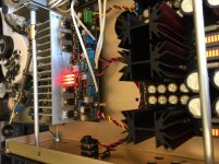
It does not look like a main board electronics build issue indeed. It seems like a signal path and grounding issue.
Don't wire the IEC mains ground or other ground to an RCA's ring. I see a yellow/green wire to one in your photo that I don't know what is it for. Remove it.
Wire the IEC mains ground to a nearby chassis location with a short thick cable to a screw with a safety nut.
Install another chassis screw in the space between boards. Wire there a link from anywhere at the selector board's signal ground. Also wire links to the same chassis screw from both DCSTB's output connector's middle zero screw. Not necessarily the perfect grounding scheme for you but something to start with.
I hope you have a stereo unswitched jack type. If the jack is proper, or more complex but rewired properly for TRS only and still no correct headphones sound, trace the signal on both channels from input to output and see where it possibly stops so to fix or rewire as we discussed in a previous post.
Attachments

...hmm, that's strange.
Rechecked the voltages, and all is as reported earlier, with the exception of R2 and R4 on one side. R2 (was .18V) is now .35V and R4 (was .50V) is now .17V. And the bottom LED bar appears a bit dimmer, but maybe that's just me.
in
20.4Vac in.
out
-17.35V
+17.36V
+17.70V
-17..46V
Rechecked the voltages, and all is as reported earlier, with the exception of R2 and R4 on one side. R2 (was .18V) is now .35V and R4 (was .50V) is now .17V. And the bottom LED bar appears a bit dimmer, but maybe that's just me.
in
20.4Vac in.
out
-17.35V
+17.36V
+17.70V
-17..46V
That's not a good new indication. You tested that section's output with the 150-220 Ohm dummy load and then something changed or you did nothing?
With the PSU powered off and a DMM in Ohm mode compare RDS of J1 & J2. I.e. measure the resistance between drain and source pins for both without desoldering them. So we see if J2 is still well or shorted. J2 should be showing RDS in the vicinity of J1. Else replace it. Measure those same spot voltages again. If not good replace Q4. Measure those same spot voltages again. If good and Q3's sink still getting little warm load with the dummy and see if it gets hotter while the output reads steady with just little possible drop than previous output.
With the PSU powered off and a DMM in Ohm mode compare RDS of J1 & J2. I.e. measure the resistance between drain and source pins for both without desoldering them. So we see if J2 is still well or shorted. J2 should be showing RDS in the vicinity of J1. Else replace it. Measure those same spot voltages again. If not good replace Q4. Measure those same spot voltages again. If good and Q3's sink still getting little warm load with the dummy and see if it gets hotter while the output reads steady with just little possible drop than previous output.
Install another chassis screw in the space between boards. Wire there a link from anywhere at the selector board's signal ground. Also wire links to the same chassis screw from both DCSTB's output connector's middle zero screw. Not necessarily the perfect grounding scheme for you but something to start with.
Hi Salas, the above grounding scheme works fine for me so now stereo sound noise free. I am using Audiotechnica ATW1000 and sound very nice. Thanks again.
Quan
- Home
- Source & Line
- Analog Line Level
- Salas DCG3 preamp (line & headphone)