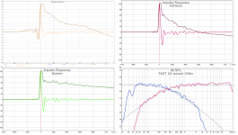
I found a setting in Najda for the "DAC interpolation filter roll-off" and changed it from fast to slow. I then changed the acoustic crossover from 500 to 800 (some weird dip at 400 not related to crossover made it difficult to measure what was going on) and dialed in a quick and dirty Harsch.
STEP goes to 900µsec now......
I also downloaded rephase so I might get some FIR-action going next week we'll see how that goes.
Happy Christmas everyone
Thanks, your new setting helped some.
For comparison found some old measurements that involve UMIK-1 microphone and tweeter 10F/8424 setup as FAST with first order XO and put those plots beside your last one.
Attachments
Hello,
I have a question.
Scenario is this:
1. Set the low pass filter for the mid as a 2nd order Bessel at central frequency, fc for the XO centerpoint.
2. Set the high pass filter for the tweeter as a 4th order Butterworth at fc.
Question: i will add the delay to the tweeter or substract it ? (delay of the tweeter equal to 1/2 of the period of one cycle at fc).
Is this still a Harsch Crossover?
I think Byrtt showed earlier in his electrical loop back experiment that flipping the Bessel 2 and BW4 doesn't work. The low pass has to be BW4 and the low pass on the tweeter has to be Bessel 2 for it to be a Harsch XO. You can try it the other way, but it is no longer a Harsch - it is in-named but the performance on phase and step response is not as good.
It would be nice if that were possible as I know a lot of tweeters like 4th order high pass to keep distortion low. So to do this, the tweeter needs to be XO'd about 2x higher than then usual minimum point if it does not have a low fs and wide bandwidth with low distortion.
I found the rather cost effective Dayton DC28F-8 able to achieve a textbook Bessel 2 at 1.7kHz in electro-acoustic target using a 1st order BW filter (probably circa 2kHz).
Other 28mm soft or Al/Ti domes can probably do this as well.
Yes, that is the reason i asked.
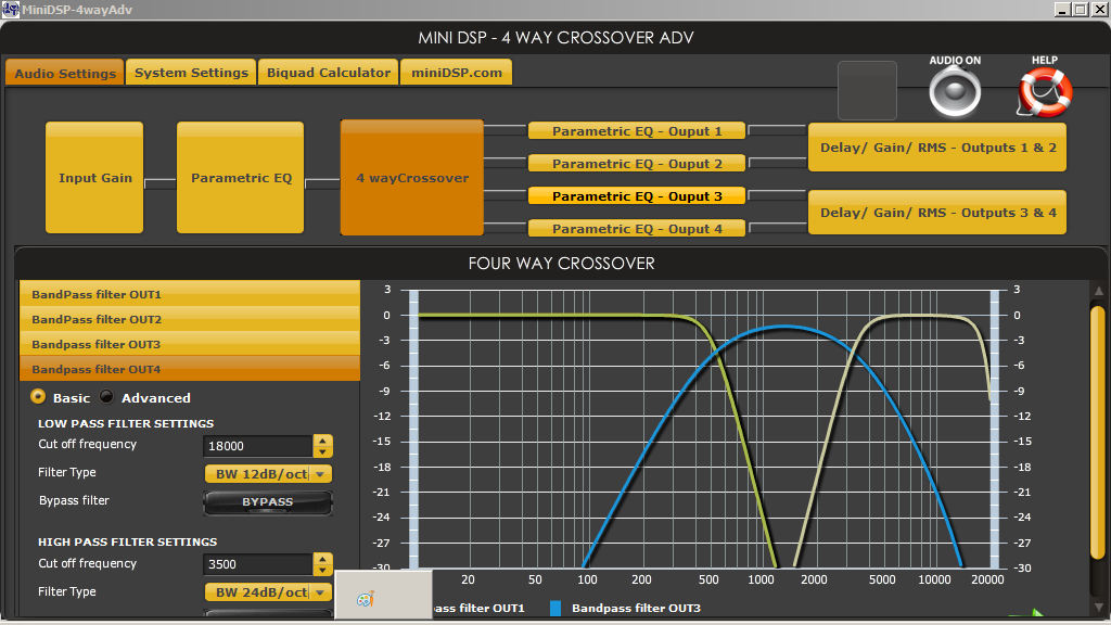
In the first posts you posted a picture from MiniDSP settings showing a 3way crossover. I did this and i sweat it sounds incredible.
Just the note that i subtract the delay, not added it, for the tweeter.
I have no measurements.
In the first posts you posted a picture from MiniDSP settings showing a 3way crossover. I did this and i sweat it sounds incredible.
Just the note that i subtract the delay, not added it, for the tweeter.
I have no measurements.
Arcgotic,
What drivers are you using and is that BW4-BES2-BES2-BW4 (electrical) XO pictured? I have tried that too and it does work and sounds quite good. It will not have as flat a phase as a true Harsch, but is probably better than symmetric LR4 or LR2 - closer to an asymmetric hole filler 3 way.
What drivers are you using and is that BW4-BES2-BES2-BW4 (electrical) XO pictured? I have tried that too and it does work and sounds quite good. It will not have as flat a phase as a true Harsch, but is probably better than symmetric LR4 or LR2 - closer to an asymmetric hole filler 3 way.
.....I did this and i sweat it sounds incredible.
Just the note that i subtract the delay, not added it, for the tweeter.
I have no measurements.....
As diy'er feel free to do whatever that sounds incredible.
But think be a bit careful and try to get some measurements to back up so that one not gets used to a sound that can happen be very wrong.
Xrk, i use that for H frame OB 15" bass, 220Hz tractrix horn loading a 3.5" full range , and some Philips tweeters.
I'll measure, at this moment i don't have a good microphone.
I'll measure, at this moment i don't have a good microphone.
Is there a way to extend this to a 4-way? Sorry if this has already been talked about, but I was thinking
Sub 4th order BW low pass
Midbass second order bessel band pass
Mid-tweet fourth order BW highpass, bessel second order low pass
Super tweet fourth order BW highpass
Would that work to extend the theory to 4-way?
Sub 4th order BW low pass
Midbass second order bessel band pass
Mid-tweet fourth order BW highpass, bessel second order low pass
Super tweet fourth order BW highpass
Would that work to extend the theory to 4-way?
maggieesnmacs,
Haven't got time today but can sim your suggestions tomorrow if you support me data where to place XO frq points and what your theoretical speaker systems stop bands are at. On forehand I'm a bit skeptical to get so many XO points to behave good smooth frq and timing response as was it a one driver system, 4-way will probably need more intelligent DSP engine with build in options to control delays and also have FIR filters at hand to get smooth frq and timing response so as to behave as a one driver good IRR system.
Haven't got time today but can sim your suggestions tomorrow if you support me data where to place XO frq points and what your theoretical speaker systems stop bands are at. On forehand I'm a bit skeptical to get so many XO points to behave good smooth frq and timing response as was it a one driver system, 4-way will probably need more intelligent DSP engine with build in options to control delays and also have FIR filters at hand to get smooth frq and timing response so as to behave as a one driver good IRR system.
maggieesnmacs,
Haven't got time today but can sim your suggestions tomorrow if you support me data where to place XO frq points and what your theoretical speaker systems stop bands are at. On forehand I'm a bit skeptical to get so many XO points to behave good smooth frq and timing response as was it a one driver system, 4-way will probably need more intelligent DSP engine with build in options to control delays and also have FIR filters at hand to get smooth frq and timing response so as to behave as a one driver good IRR system.
I know it won't behave quite like one driver but figured I might as well get as close as possible while I'm at it. I'm using the 4x10hd minidsp. The xo points will be 120hz, 400hz, 8khz. My plan is to have a speaker with the crossover way out of the most sensitive region. And what are the speaker stop bands?
I know it won't behave quite like one driver but figured I might as well get as close as possible while I'm at it. I'm using the 4x10hd minidsp. The xo points will be 120hz, 400hz, 8khz. My plan is to have a speaker with the crossover way out of the most sensitive region. And what are the speaker stop bands?
Speaker system stop bands are HP and LP of system and normal considered a BW2 slope, LP is f3 point of your tweeter and HP is room and placement dependent probably in area 15-40Hz (Woofer). I need those because with 3x IRR XO points (4x IRR band passes) inside audio band they push to each other slopes learned over at Rephase thread and Linkwitz website. Thoughts having XO out of sensitive region think is good thinking, example smooth or linear phase at your 120/400Hz XO points will give realism to sound picture is own experience where the 8kHz XO point is so high where speakers no matter what can't reproduce square waves in lack of bandwidth that then needs to reach up in 100-300kHz area as amps can do.
Speaker system stop bands are HP and LP of system and normal considered a BW2 slope, LP is f3 point of your tweeter and HP is room and placement dependent probably in area 15-40Hz (Woofer). I need those because with 3x IRR XO points (4x IRR band passes) inside audio band they push to each other slopes learned over at Rephase thread and Linkwitz website. Thoughts having XO out of sensitive region think is good thinking, example smooth or linear phase at your 120/400Hz XO points will give realism to sound picture is own experience where the 8kHz XO point is so high where speakers no matter what can't reproduce square waves in lack of bandwidth that then needs to reach up in 100-300kHz area as amps can do.
OK so just the f3 points of the speaker system. The woofer should be about 45hz in its sealed box, but I will most likely eq the low end down to an f3 of about 30hz. The f3 of the tweeter im guessing is ~25khz. It doesn't show in the datasheet, it cuts off at 20k :/
Wow... this thread has been going for quite a while. I don't know if others have pointed out some flaws in this approach. Basically, you should never optimize for any other parameter over the on-axis frequency response. Even if we set this principle aside for a minute, there are still quite a few problems in the application of this technique to different configurations.
The phase relationship between two drivers on a baffle depends on a number of things, such as the inter-driver distance, driver roll-offs and the crossover topology. You simply cannot apply the rules in first post to any configuration and expect to get reasonable results.
I would suggest looking at this thread for an overview of what makes a truly great crossover:
Crossover mods for the AR4x - Mods, Tweaks, and Upgrades to the Classics - The Classic Speaker Pages Discussion Forums
In a crossover, the only thing that matters is the relative phase of one driver compared to the other. Phase is simply the relative difference in arrival time of a frequency compared to some reference. Let's assume the arrival of 2kHz from the woofer is at time t=5 ms. Now, if the tweeter arrival is at t= 6 ms, then the phase difference is calculated as:
time difference in arrival = 1 ms
1 cycle at 2kHz frequency = 0.0005 seconds, which is also equal to 360 degrees (1 cycle rotation).
How many degrees in 1 ms at 2kHz?
1/1000 (seconds) x 0.0005 x 360 = 180 degrees.
That's it. If your crossover can make up 180 degrees in the right direction, you will be exactly in phase at 2kHz.
Of course, the real situation is more complicated. But the name of the game is phase overlap through the crossover region. That's how you get seamless integration.
I'll get off the soapbox. I'm sure you know all this. I just wonder why you would sacrifice the on-axis response, which matters a great deal, for apparent time coherency, which has been show to not matter so much.
Now, you might say that I must hear it to believe it. But my own system has a near flat amplitude and phase. Yes, coherent time arrival is important, but not at the expense of amplitude. Get the frequency response right first, then see about the phase.
EDIT: I'm a beer down, so forgive me for any math errors.
Last edited:
Harsch doesn't have phase wrap - it's almost flat linear with a 55deg rise and fall - not a 180 deg phase wrap. That means you have at least a hope of reproducing and square wave whereas LR2 and LR4 cannot hope to do so.
The percussion and plucked strings, piano all sounds more realistic with a Harsch vs LR. Phase is important - I agree and phase is better with Harsch. You have mild frequency response ripples but that does not equate to phase not tracking or not linear.
The percussion and plucked strings, piano all sounds more realistic with a Harsch vs LR. Phase is important - I agree and phase is better with Harsch. You have mild frequency response ripples but that does not equate to phase not tracking or not linear.
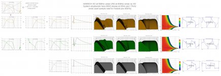
Because i had some theory models into REW close to Bob Brines FAST build ( http://www.diyaudio.com/forums/full-range/287478-what-i-am-taking-lsaf-6.html#post4739628 ) and ra7 after a beer down : ) question Harsh XO will share these visuals. Admit haven't listen to Harsch XO myself because have DSP engine with plenty filter tools to fully repair/correct amplitude or time domain, but think of Harsch XO as a clever compromise for builders who prefer or is limited to IRR filters combined physical or digital delay for driver offset.
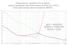
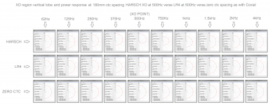
Find below data Harsch XO compared to LR4 and no XO, for me it looks Harsch wins in waterfalls having cleaner mids as the no XO model. Being not in phase at XO point (see phase plot) as LR4 it has more complicated tilted lobe in vertical XO region as with 1st order filters but think power response in XO region looks be as relative good as LR4 perform.
Find below data Harsch XO compared to LR4 and no XO, for me it looks Harsch wins in waterfalls having cleaner mids as the no XO model. Being not in phase at XO point (see phase plot) as LR4 it has more complicated tilted lobe in vertical XO region as with 1st order filters but think power response in XO region looks be as relative good as LR4 perform.
Attachments
Last edited:
Yes, more info here:
http://www.diyaudio.com/forums/multi-way/277691-s-harsch-xo.html
It is the target electro-acoustic transfer function, not the electrical only function. So it may require for example a first order electrical to get second order Bessel for high pass. The 4th order BW lowpass is usually one and the same for a woofer.
First EQ all responses as flat as possible with no filters and minimize use of boost eq.
On a 4 way it would go like this:
Subwoofer: BW4 LPF @ Freq_XO1, (optional LPF for infrasonic protection but avoid as it adds group delay)
Midbass: BES2 HPF @ Freq_XO1, BW4 LPF @ Freq_XO2, delay = 1/(2*Freq_XO1),
Midrange: BES2 HPF @ Freq_XO2, BW4 LPF @ Freq_XO3, delay = {1/(2*Freq_XO2)+1/(2*Freq_XO1)},
Tweeter: BES2 HPF @ Freq_XO3, delay = {1/(2*Freq_XO3)+1/(2*Freq_XO2)+1/(2*Freq_XO1)},
Typical Frequencies would be Freq_XO1=80Hz, Freq_XO2=800Hz, Freq_XO3=2.5kHz to 4.5kHz (to taste and to avoid tweeter distortion)
All drivers +ve polarity.
asked it because i did not received 2way harsch-like step response on 4way
asked it because i did not received 2way harsch-like step response on 4way
You have tried it with a 4 way?
Do it in smaller steps. Tweeter with mid first get that to work. Then add mid bass and get that to work. As you add mid bass note that delays have to be applied to the mid+tweet combo together. Then add subwoofer and note delay has to be added to mid bass + mid + tweeter combo together. The delays are tricky because they don't include acoustic offsets that are native to the drivers. You can either measure the offsets via usual acoustic interferometry and simulation. Or guess what it is and fine tune delays by watching individual and combination step responses.
yea i have that xo still on my module list.
just asking has anybody else tried this on 4way?
my xo´s what ive done if alignment of tweeter and mid is correct step starts to seem ok, bass can be quite a lot wrong and it still look good step response.
just asking has anybody else tried this on 4way?
my xo´s what ive done if alignment of tweeter and mid is correct step starts to seem ok, bass can be quite a lot wrong and it still look good step response.
Last edited:
...just asking has anybody else tried this on 4way?...
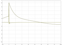
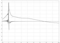
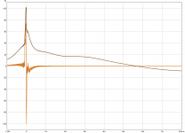
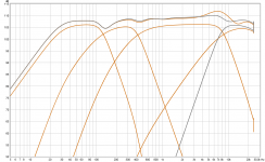
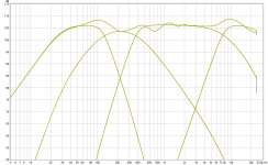
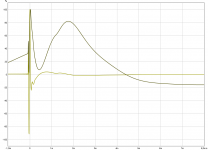
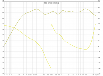
Not other than some theory modeling and think it gets into compromise chaos when following Harsch XO rules for summing so many narrow pass bands. Brown traces below is following rules and did quickly find that high pass tweeter BW4 (gray traces) instead of BS2 is better and some slopes can maybe get improved by smarter people than me, or by real world drivers inherent response that can end system sum better than this theory model. I'm not too optimistic to get it real good for multi-way in that think of Harsch XO type as a compromise way to TP as seen post 275. Picture 2 and 3 IR/SR is related to 4-way plot picture 1, and picture 4 is better data in Harsch executed as 2-way with same system stop band roll offs as the other two.
Attachments
OK so just the f3 points of the speaker system. The woofer should be about 45hz in its sealed box, but I will most likely eq the low end down to an f3 of about 30hz. The f3 of the tweeter im guessing is ~25khz. It doesn't show in the datasheet, it cuts off at 20k :/
Sorry so late, it will make sound but think is some big compromise when run as theory model, although changing low pass slope for mid to BW4 will help as seen in previous post, and also maybe real world drivers inherent response and dispersion will show better than theory model.
Attachments
- Home
- Loudspeakers
- Multi-Way
- S. Harsch XO