Byrtt,
Try XO points at 200Hz, 1000Hz, and 4000Hz. I think most tweeters can handle 1st order electrical to get 2nd order acoustic of 4000Hz xo.
Although my feeling is that 3 way is best with B&O hole filler to which you make the upper 3 drivers have Bessel 2 high pass and subwoofer 4th order low pass with Harsch. So Hybrid Harsh and Hole Filler 4 way.
Because properly implemented 3 way as B&O Hole filler will behave as one big full range driver. To which we apply Harsch to integrate it with sub woofer.
Last edited:
If you use a first order filter at 4Khz the slope will only give you 6db down at 2khz and 12db down at 1Khz. Some tweeter would probably not take to kindly to much output at 1Kz
The B&O Hole Filler XO would be -12dB/octave on the tweeter. It's 6dB/octave on both sides of the mid. But a good full range can handle that just fine.
So -24dB at 1kHz on the tweeter.
So -24dB at 1kHz on the tweeter.
Byrtt,
Try XO points at 200Hz, 1000Hz, and 4000Hz. I think most tweeters can handle 1st order electrical to get 2nd order acoustic of 4000Hz xo...
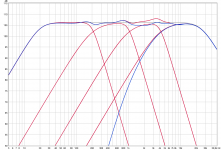
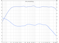
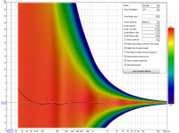
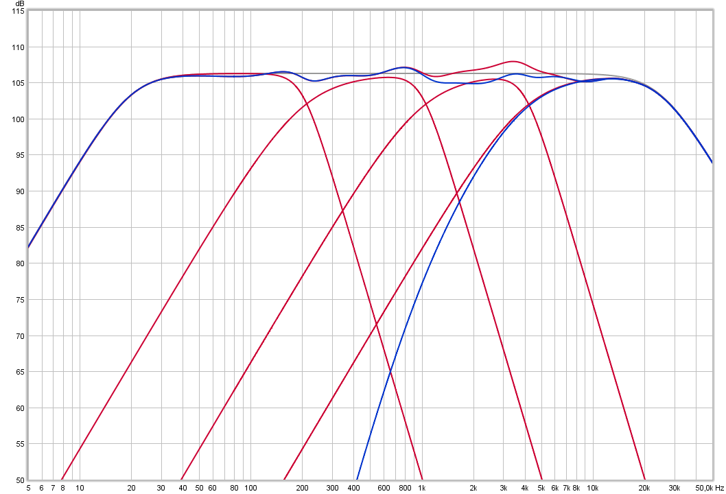
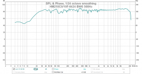
Okay this got better after some more exercise and hard thinking 🙄 previous XO points was based maggieesnmacs setup XO points at 120Hz/400Hz/8kHz with BW2 system stop bands at 30Hz and 25kHz, X request XO points at 200Hz/1kHz/4kHz and was combined BW2 system stop bands at 20Hz and 25kHz. Previous model was based on 48kHz IR-wav files this is based on 384kHz IR-wav files and makes a difference, what the exercise and thinking was about is if its needed to build in slopes from other neighbor pass bands slopes too, and doing it for tweeter helped. That makes woofer/mid-woofer/mid is standard acoustic target slopes BS2 HP and BW4 LP, but tweeter HP slope have multiple slopes in BW2 20Hz + BS2 200Hz + BS2 1kHz + BS2 4kHz, and as seen below that helps smooth system sum looking at blue trace verse red.
Attachments
Kindhornman,
Yes, and if both positive phase 2nd order then there is a cancellation "hole" at the xo frequency. The positive midrange with 1st order slopes fill in that hole mathematically perfect.
More info here:
http://www.diyaudio.com/forums/multi-way/88135-filler-driver-ala-b-o-3.html
Yes, and if both positive phase 2nd order then there is a cancellation "hole" at the xo frequency. The positive midrange with 1st order slopes fill in that hole mathematically perfect.
More info here:
http://www.diyaudio.com/forums/multi-way/88135-filler-driver-ala-b-o-3.html
Last edited:
Okay this got better after some more exercise and hard thinking 🙄 previous XO points was based maggieesnmacs setup XO points at 120Hz/400Hz/8kHz with BW2 system stop bands at 30Hz and 25kHz, X request XO points at 200Hz/1kHz/4kHz and was combined BW2 system stop bands at 20Hz and 25kHz. Previous model was based on 48kHz IR-wav files this is based on 384kHz IR-wav files and makes a difference, what the exercise and thinking was about is if its needed to build in slopes from other neighbor pass bands slopes too, and doing it for tweeter helped. That makes woofer/mid-woofer/mid is standard acoustic target slopes BS2 HP and BW4 LP, but tweeter HP slope have multiple slopes in BW2 20Hz + BS2 200Hz + BS2 1kHz + BS2 4kHz, and as seen below that helps smooth system sum looking at blue trace verse red.
Oh that looks much better - thank you, Byrtt.
This is actually pretty significant. I think this is the first time I have seen a Harsch XO demonstrated (via DSP loop back experiment) for a 4 way speaker.
Last edited:
...Although my feeling is that 3 way is best with B&O hole filler to which you make the upper 3 drivers have Bessel 2 high pass and subwoofer 4th order low pass with Harsch. So Hybrid Harsh and Hole Filler 4 way.
Because properly implemented 3 way as B&O Hole filler will behave as one big full range driver. To which we apply Harsch to integrate it with sub woofer.
Agree idea use Harsch for subwoofer think is great 🙂 regarding filler performance as one big full range driver except measured right on design axis I'm sceptic 😛 but admire energy.
Oh that looks much better - thank you, Byrtt.
This is actually pretty significant. I think this is the first time I have seen a Harsch XO demonstrated (via DSP loop back experiment) for a 4 way speaker.
Yes it looks much better and probably because those band passes is better distributed and wider than the one for maggieesnmacs, that said think we shall be fair and admit it ain't really smooth and studies seem tell that FR is king to have right, so stay two-way Harsch if possible or use FIR, unlesh drivers inherent response combined enclosure design can benefit XO summing is unsmooth.
You probably forgot but i have told before that half a year ago i changed to use IR-wav files of band passes created in Rephase, then in "All SPL" tab into REW you can do the math plus/minus/times/over to sum them and offset is done in "Impulse" tab before the summing. This way spare quite some time compared before with real electric DSP loops and result is same.
You probably forgot but i have told before that half a year ago i changed to use IR-wav files of band passes created in Rephase, then in "All SPL" tab into REW you can do the math plus/minus/times/over to sum them and offset is done in "Impulse" tab before the summing. This way spare quite some time compared before with real electric DSP loops and result is same.
Cool, that sounds like something I could try. Going to fiddle with it right now 🙂. If i can then export the frd files from REW I might be able to load them in boxsim as "driver as measured in box" and sim the theoretical lobing.
Yes it looks much better and probably because those band passes is better distributed and wider than the one for maggieesnmacs, that said think we shall be fair and admit it ain't really smooth and studies seem tell that FR is king to have right, so stay two-way Harsch if possible or use FIR, unlesh drivers inherent response combined enclosure design can benefit XO summing is unsmooth.
You probably forgot but i have told before that half a year ago i changed to use IR-wav files of band passes created in Rephase, then in "All SPL" tab into REW you can do the math plus/minus/times/over to sum them and offset is done in "Impulse" tab before the summing. This way spare quite some time compared before with real electric DSP loops and result is same.
I'm doing that same trick to find working recipes for the cross talk 🙂. My PC is literary scattered with several tries. Once I find something I replicate it in JRiver DSP and test that with Dirac pulses and output to file, check it in REW. Then on to listening with the actual setup.
I haven't looked through this thread but I did take a peak at the referenced paper (don't read the langue) in the first post. I don't know if anyone has pointed this out but this is really no different that the approach used John Bau of Spica Speakers back in the 80's. The basic differences what that John used a Bessel low pass rather that a Butterworth and the tweeter delay was controlled by offset. This allowed a completely passive implementation of the speaker/crossover. Additionally, the Bessel low pass is superior to the Butterworth since it has maximally flat GD. The choice of high pass really doesn't matter so much as none of the conventional (Butterworth, Linkwitz, Bessel) HP sections have constant GD. Anyway, just a though. Harsch seems like a re-hash of past work. If it's been noted before, ok.
I actually like BW4 for the woofer low pass as it stomps out any possible woofer cone breakup from leaking through. I also use mechanical movement of the tweeter to get the time delay. It becomes impractical for lower xo frequencies though as the distance is very large for a 600Hz XO.
There are a lot of combinations that may give quasi transient perfect. The Harsch just happens to use two very easy to implement filters and choice of BW4 for woofer had practical implications for reducing cone breakup from leaking through.
There are a lot of combinations that may give quasi transient perfect. The Harsch just happens to use two very easy to implement filters and choice of BW4 for woofer had practical implications for reducing cone breakup from leaking through.
I actually like BW4 for the woofer low pass as it stomps out any possible woofer cone breakup from leaking through. I also use mechanical movement of the tweeter to get the time delay. It becomes impractical for lower xo frequencies though as the distance is very large for a 600Hz XO.
There are a lot of combinations that may give quasi transient perfect. The Harsch just happens to use two very easy to implement filters and choice of BW4 for woofer had practical implications for reducing cone breakup from leaking through.
So I'm seriously considering this as a project, and am hoping to do a passive as well as active version. I'm looking at your RS225 and TC9FD monitor (obvious upgrade path to 10F if I feel like it) and am wondering how far the physical offset would be... I am somewhat flexible with the crossover point and am considering machining a waveguide (There's a giant CNC machine at my work) to get the physical offset - there's practical limits at work with c-c spacing and depth of waveguide of course, just hoping to get an answer as to whether it is practically feasible.
I have nothing fixed yet other than the drivers (on their way already) and am hoping to get a reference standard transient perfect monitor or possibly compact floor stander (optimally damped TL).
For a 500Hz Harsch crossover frequency, 1ms is the delay needed (not including driver offset, which is about 15mm to 25mm typically for a full range and a 8in woofer.
1ms x 342m/sec = 342mm or 13.5in offset. You would need a horn or waveguide to do this. So the higher the XO freq, the shorted the offset to achieve the delay.
1ms x 342m/sec = 342mm or 13.5in offset. You would need a horn or waveguide to do this. So the higher the XO freq, the shorted the offset to achieve the delay.
So that's beginning to look quite impractical then... Adjusting xover point to reduce z offset means higher freq, a larger c-c distance, diffraction effects start coming into play as well, directivity starts becoming a factor... Hrmmm, seems like passive might be a big ask in this case...
Are there any examples of a practical passive transient perfect FAST? Or is it just the requirements of the harsch xo that bring this up?
Are there any examples of a practical passive transient perfect FAST? Or is it just the requirements of the harsch xo that bring this up?
Last edited:
https://dl.dropboxusercontent.com/u/33080121/hifi/pikkujoulu/xos.mdat
there is some measurements from my xo´s
-harsch
-1butter
-linear phase
-2LR
feel free to compare, measured near listening spot
there is some measurements from my xo´s
-harsch
-1butter
-linear phase
-2LR
feel free to compare, measured near listening spot
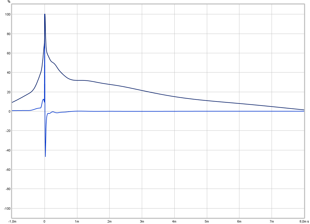
I did some more playing with XO's yesterday. Overall comment it is very difficult to get the perfect triangle impulse response, but easy to get an impulse with no ringing. The latter is good enough.
I did a comparison between a 500Hz Harsch and a 500Hz BW6. The graphs are quite similar, but the sound is worlds apart. The BW6 sound stage lacked depth, while the Harsch had great depth. I'm sure that you all have a copy of it 😉, but I listened to the Vivaldi RV552 and with the Hasch, the echo violin was way back in the hall, while with the BW6, all four violins were in a line at the front of the stage.
I did not expect that much difference. It is all phasing.
Bob
Attachments
-
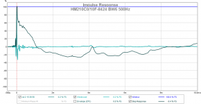 HM210C0-10F-8424 BW6 500Hz Impulse.png55.9 KB · Views: 473
 -
 HM210C0-10F-8424 BW6 500Hz.png32.3 KB · Views: 474
 -
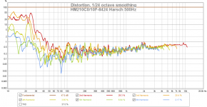 HM210C0-10F-8424 Harsch 500Hz Distortion.png140.6 KB · Views: 472
 -
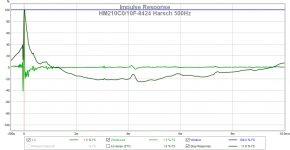 HM210C0-10F-8424 Harsch 500Hz Impulse.png57.4 KB · Views: 480
 -
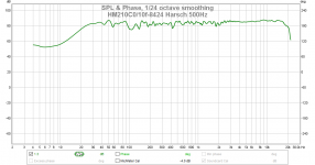 HM210C0-10F-8424 Harsch 500Hz.png31.1 KB · Views: 477
 -
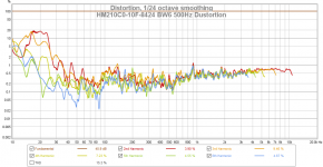 HM210C0-10F-8424 BW6 500Hz Dustortion.png135.1 KB · Views: 199
Hello Erik, no good woman to be had in town, on my list or next door.
Hello all, i will generalize this topic now.
An allpass of first order and a second order Bessel high- or lowpass have a pretty constant delay below transit frequency, where half phase turn. With these filters, delay time peaks only at zero frequency(, like with Butterworth filters, amplitude peaks either at zero or infinite frequency). But this delay is already that uneven around transit frequency, that its unevenness is beyond possibility of repair using Maxwell's classics. (Only a purely first order crossover is a classical flat phase one.)
Yet using such a spoiled lowpass, and in order to yet obtain flat phase for the crossover sum, highpass path must become delayed. A constant delay is not classic, as speed of light is too great. Highpass must have lower order than lowpass, for now first order, so it can smoothe the transit. I am gonna apply such a crossover in Natural and obtain a transient response which does not sound classic or relative but just natural.
Mister or Misses Harsch used steeper slopes of LP 4th and HP 2nd but still went for flat phase. He obtained a more relative and erratic but still good response.
As i am gonna, Dommii's Big Wumpe uses a horn for highpass delay. At him, high order lowpass also delays lowpass path, hence the result is not as relative as at Harsch's but more classic, with Pi phase turn around crossover point.
Glad to have got this off my mind. Uli
Read through and found this to be very very interesting.Thanks a lot for going into so many details.I am planning to try it in my car using a 6.5 inch Midbass and a 2 Inch Full range. the Fc is going to be 1000Hz. I kind of understood everything except the delay on the Fullrange as we have different delays in car due to speakers being not equidistant from the listener. Any ideas to achieve the same will be highly appreciated.
- Home
- Loudspeakers
- Multi-Way
- S. Harsch XO