Yes I'd like to see that.
We can even compare it to a sweep of your PC soundcard feeding the amp directly. Thus getting the Nadja out of the picture for a comparison.
Keep it impulses, no need for the STEP yet, or impulse plus step for a single driver might work.
We can even compare it to a sweep of your PC soundcard feeding the amp directly. Thus getting the Nadja out of the picture for a comparison.
Keep it impulses, no need for the STEP yet, or impulse plus step for a single driver might work.
Zschimmel,
Sorry you are having so many issues with your signal chain upstream. I think we are making progress though and the latest impulses are starting to look better. It must be a timing or digital conversion issue. It's good to simplify and make things as basic as possible to debug and you did the right thing to go back to as basic as possible.
One thing I was lucky with is that from a signal standpoint, a miniDSP and a TPA3116D2 amp were the only things in my signal path. The signal for the sweep was from my PC's sound card headphones out. Luckily, I never had these pre-ring or pre-pulse issues. Each time I had an IR or SR that looked strange, Byrtt would come to the rescue and showed me theoretically why it looked the way it did and it was always based on the band limits and filter shapes.
10F fullrange no crossover filters, sweeps from 100-24000
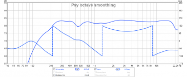
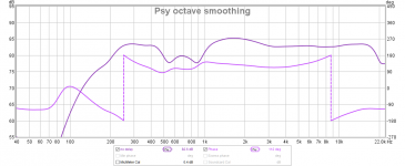
Looks like Najda is the culprit...


I have to clean up and get ready to go to my mothers for Christmas eve. I'll do some measurements without the backplate tomorrow or the day after to see if that is causing it. Otherwise I think I better contact Chapark to see what's wrong.
Happy holidays and thanks for the help everyone.
Looks like Najda is the culprit...
I have to clean up and get ready to go to my mothers for Christmas eve. I'll do some measurements without the backplate tomorrow or the day after to see if that is causing it. Otherwise I think I better contact Chapark to see what's wrong.
Happy holidays and thanks for the help everyone.
Last edited:
Wow - that's a drag that such a nice DSP processor has such an artifact of reverse pre-ring. I wonder if there is a setting in Najda that does this. I have noticed that a sharp reverse pre ring happens when I have a brick wall band stop on other side. The electronics have no choice but to do a massive pre-ring achieve such a tight band stop. Is there a setting somewhere in Najda that has a brick wall band limiter? If you can't get rid of this, it's always going to be a problem to achieve proper time aligned and transient perfect speakers.
I'll throw my hat into the fray as well. I did some work with this last weekend in this thread: http://www.diyaudio.com/forums/multi-way/264998-forward-radiation-sickness-big-waveguide-cardioid-2.html#post4554449 but I thought it fit here and might get a better look.
I got back to this today, and after several hours I haven't figured it out. The impulse and step responses are shown with no delay added and they are dual channel so the offset seen is real. The combined graph with delay is with the mid delayed. I haven't see anyone successfully do this with the Bessel hp and BW4 lp flipped like I have here......maybe that won't work?
Nate,
Nice work. When you get a chance, please show the acoustic xo plot with all 3 traces and impulse and step response. Your phase variation is smooth but a lot. Your vertical axis has pretty big steps. A Harsch XO properly done is fairly flat with a circa 55 deg excursion at the xo frequency. The tell tale that the delay is close is when the combined response is a bit lower than the BW24 response of the woofer. The step response will be triangular like but sometimes has a slight rise in front of the sharp rise. When it is dialed in the percussive jump out at you. Instruments sound real like they are in the room.
I got back to this today, and after several hours I haven't figured it out. The impulse and step responses are shown with no delay added and they are dual channel so the offset seen is real. The combined graph with delay is with the mid delayed. I haven't see anyone successfully do this with the Bessel hp and BW4 lp flipped like I have here......maybe that won't work?
I'll throw my hat into the fray as well. I did some work with this last weekend in this thread: http://www.diyaudio.com/forums/multi-way/264998-forward-radiation-sickness-big-waveguide-cardioid-2.html#post4554449 but I thought it fit here and might get a better look.
I got back to this today, and after several hours I haven't figured it out. The impulse and step responses are shown with no delay added and they are dual channel so the offset seen is real. The combined graph with delay is with the mid delayed. I haven't see anyone successfully do this with the Bessel hp and BW4 lp flipped like I have here......maybe that won't work?
Earlier in this thread Byrtt showed that unless you have the filters as Woofer BW4 LPF / BES2 HPF mid BW4 LPF / BES2 HPF Tweeter, the delays won't line up right. I thought a mirror image about the mid would work but I guess not.
Where are your graphs?
Yeah that's what I thought.
Hmm, not sure why the graphs didn't post they were there in the preview.
Hmm, not sure why the graphs didn't post they were there in the preview.
I got back to this today, and after several hours I haven't figured it out. The impulse and step responses are shown with no delay added and they are dual channel so the offset seen is real. The combined graph with delay is with the mid delayed. I haven't see anyone successfully do this with the Bessel hp and BW4 lp flipped like I have here......maybe that won't work?
Quoting myself to avoid re-typing the details. Here's the data.
Attachments
xrk971 and natehansen66,
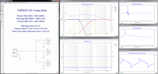
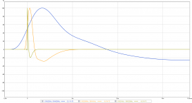
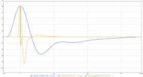
3-way HARSCH band pass:
BW2/20Hz-BW4/200Hz
BS2/200Hz-BW4/1kHz
BS2/1kHz-BW2/20kHz
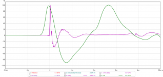
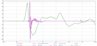
Picture 1 the three drivers firing in sync without any offset.
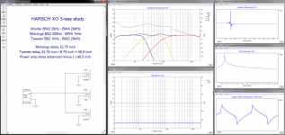
Picture 2 offset as in HARSH rule 0,5 x XO point frq.
Picture 3 manual tweaking of offset that gives less ripple while IR/SR still stays fine. This manual tweak is not necessary for original HARSH 2-way which is more flat with rule 0,5 x XO point frq, suspect its because the two XO points is relative close and 200Hz XO point hasn't settled real flat before we add a new 1kHz XO point.
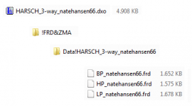
Attached is dxo-file in a zip-folder to open in XSim but because of zip file extension space limitation have it uploaded as dot-asc, therefor reneame extension to dot-zip and extract the 5Mb dxo file.
3-way HARSCH band pass:
BW2/20Hz-BW4/200Hz
BS2/200Hz-BW4/1kHz
BS2/1kHz-BW2/20kHz
Picture 1 the three drivers firing in sync without any offset.
Picture 2 offset as in HARSH rule 0,5 x XO point frq.
Picture 3 manual tweaking of offset that gives less ripple while IR/SR still stays fine. This manual tweak is not necessary for original HARSH 2-way which is more flat with rule 0,5 x XO point frq, suspect its because the two XO points is relative close and 200Hz XO point hasn't settled real flat before we add a new 1kHz XO point.
Attached is dxo-file in a zip-folder to open in XSim but because of zip file extension space limitation have it uploaded as dot-asc, therefor reneame extension to dot-zip and extract the 5Mb dxo file.
Attachments
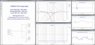
That third one looks really nice Byrtt.
Thanks!
I might just have to take out my old 3-way xo study OB speaker to try this out.
Thanks!
I might just have to take out my old 3-way xo study OB speaker to try this out.
That third one looks really nice Byrtt.
Thanks!
I might just have to take out my old 3-way xo study OB speaker to try this out.
Welcome and yes maybe good idea to try OB speaker with this filter it will give other power response lobe scheme in XO region than the old setup which i think recall was B&O filler, you welcome request XSim plots and target files for other XO points.
Cool thanks for that BYRTT....it'll give me something to play with in xsim. I downloaded it back when bwaslo released it but haven't played with it till now. Unfortunately my compression driver can't do a 2nd order Bessel hp but playing with an idealized response will be a good learning experience.
Cool thanks for that BYRTT....it'll give me something to play with in xsim. I downloaded it back when bwaslo released it but haven't played with it till now. Unfortunately my compression driver can't do a 2nd order Bessel hp but playing with an idealized response will be a good learning experience.
It is not the named electrical filter that matters anyway. It's all about hitting the acoustical target of that specific named slope that's important. How you get there and with what electrical slope(s) does not matter at all.
No 2 drivers are going to react the same to a 2nd order Bessel electrical filter anyway. So that makes these textbook curves very convenient as these are spot on.
10F fullrange no crossover filters, sweeps from 100-24000
Looks like Najda is the culprit...
View attachment 521052
View attachment 521053
View attachment 521054
I have to clean up and get ready to go to my mothers for Christmas eve. I'll do some measurements without the backplate tomorrow or the day after to see if that is causing it. Otherwise I think I better contact Chapark to see what's wrong.
Happy holidays and thanks for the help everyone.
I kind of feared for that but there's got to be a reason for it. I'm sure we can find out why and we'll be on our way again 😉. Enjoy your Christmas.

I found a setting in Najda for the "DAC interpolation filter roll-off" and changed it from fast to slow. I then changed the acoustic crossover from 500 to 800 (some weird dip at 400 not related to crossover made it difficult to measure what was going on) and dialed in a quick and dirty Harsch.
STEP goes to 900µsec now.


I also downloaded rephase so I might get some FIR-action going next week we'll see how that goes.
Happy Christmas everyone
STEP goes to 900µsec now.
I also downloaded rephase so I might get some FIR-action going next week we'll see how that goes.
Happy Christmas everyone
Cool thanks for that BYRTT....it'll give me something to play with in xsim. I downloaded it back when bwaslo released it but haven't played with it till now. Unfortunately my compression driver can't do a 2nd order Bessel hp but playing with an idealized response will be a good learning experience.
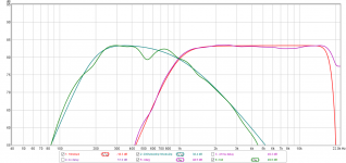
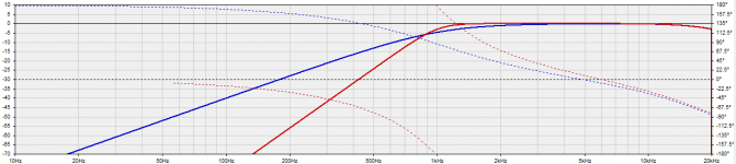
XO point 1kHz Bessel second order verse butter worth fourth order:
Guess you mean when we down at 1kHz XO point compression driver would need forth order HP filter because second order would ask it too much LF task.
You talked about taking Synergy waveguides from cellar up to living room over at that thread, guess then XO point situation will change : )
Attachments
It is not the named electrical filter that matters anyway. It's all about hitting the acoustical target of that specific named slope that's important. How you get there and with what electrical slope(s) does not matter at all.
No 2 drivers are going to react the same to a 2nd order Bessel electrical filter anyway. So that makes these textbook curves very convenient as these are spot on.
When I talk about the xo slopes I'm talking about the acoustic result and assume (often wrongly) that others are as well or know that's what I'm talking about. You won't be hitting a 2nd order anything acoustic with a wg/compression driver combo down near the bottom end of its' passband.......or any other driver for that matter unless it has something like a 1st order roll-off. I like to use rePhase to create my target curves and then use that in the "Overlay" window in REW to hit the acoustic target.
Guess you mean when we down at 1kHz XO point compression driver would need forth order HP filter because second order would ask it too much LF task.
You talked about taking Synergy waveguides from cellar up to living room over at that thread, guess then XO point situation will change : )
Yes exactly to your first point. The cd/wg combo has between a 3rd and 4th order native roll-off to begin with just below 1khz. I decided not to go any further with the Synergy experiment at this point. Working in a 20deg garage really isn't appealing which is why I had another go at the Harsch xo. When that didn't work I took the "easy way" and just created an FIR correction for my normal xo.
Yes Nate, my fault, I'm kinda slow today... must be all that food 🙁
Still it will be interesting to see how far down you actually need to follow the ideal slope for the Harsh filter to still work.
Still it will be interesting to see how far down you actually need to follow the ideal slope for the Harsh filter to still work.
- Home
- Loudspeakers
- Multi-Way
- S. Harsch XO