It's possible that there is something wrong with the old dongles i used I'll check them.
Last edited:
So I checked the cable assembly first by hooking it up to my crappy 2.1 pc speakers instead of going to line-in, listened to some music and some sines. Couldn't say there was a noticeable drop in level. I then checked the other cinch output (white) which I do not use for measuring, I always use the red one. Turns out it's a bit broken, crackes and drops the sound if you fiddle with it. Red one for measuring is fine though.
I then hooked the assembly to the mic in instead of the line in and gently remeasured.

Totally different respons, still not good though. I then fiddled a bit with the connection and measured the mic in 2 which is mostly the same but different enough to be weird.
Seems the inputs are a bit messed up or very finnecky about how the jack is in there. Since I have a umik I only use them for impedance measurements, now I know why they sometimes just fail miserably. I have done TS measuments on the 10F and 22W which come reasonably close to the published ones so it can't be completely broken.
The measurements I did with the laptop are only very slightly of from the measurements with my PC so we know the output is fine.
I have an X-Fi lying around I could try tomorrow but I remember reading somewhere it's not straightforward to get it working with REW.
I then hooked the assembly to the mic in instead of the line in and gently remeasured.
Totally different respons, still not good though. I then fiddled a bit with the connection and measured the mic in 2 which is mostly the same but different enough to be weird.
Seems the inputs are a bit messed up or very finnecky about how the jack is in there. Since I have a umik I only use them for impedance measurements, now I know why they sometimes just fail miserably. I have done TS measuments on the 10F and 22W which come reasonably close to the published ones so it can't be completely broken.
The measurements I did with the laptop are only very slightly of from the measurements with my PC so we know the output is fine.
I have an X-Fi lying around I could try tomorrow but I remember reading somewhere it's not straightforward to get it working with REW.
Hi been offline and to town shopping Christmas presents : )
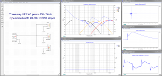
Pretty sure for LR2 polarity setup is wrong. For a second order 2 way one of the drivers shall be reversed and it could be discussed which one it is best or most correct to reverse, but reversing either woofer or tweeter will make speaker system to work so drivers don't cancel at XO point. For a second order 3 way reverse either mid or both woofer + tweeter, again it could be discussed which one it is best as for the two way. Will check up and get back with plots.
Pretty sure for LR2 polarity setup is wrong. For a second order 2 way one of the drivers shall be reversed and it could be discussed which one it is best or most correct to reverse, but reversing either woofer or tweeter will make speaker system to work so drivers don't cancel at XO point. For a second order 3 way reverse either mid or both woofer + tweeter, again it could be discussed which one it is best as for the two way. Will check up and get back with plots.
We are going to need Byrtt's help. The thing that bothers me is that changing the delay does not produce a shift of leading edge spike from the tweeter relative to the broad hump from the woofer or mid. Only the shape of the triangle seems to change. Something is not right. We maybe have to resort to looking at your mdat REW file to debug at some point.
The fact that there are 3 different amps and they all have a negative pre-spike indicates problem is non signal source.
The fact that there are 3 different amps and they all have a negative pre-spike indicates problem is non signal source.
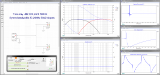
Here some documentation for LR2 that because the bands that meet at a XO point one of them need polarity reversed because this filter type is in phase trace at XO point but because second order is 180º phase turn it means frq amplitude domain will cancel out as with a driver front and back wave when not housed on a kind of baffle.
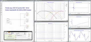
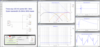
Picture 1-3 is LR3 3-way.
1. Drivers is in same polarity which ruin frq amplitude domain with two dip-notches that cancel out at XO points.
2. Mid is reversed in polarity and frq amplitude domain is perfect.
3. Tweeter and woofer is reversed in polarity frq amplitude domain is perfect.
Choose either 2 or 3 as solution but look at step response and decide if woofer shall fire forward or backward on a kickdrum, think i would choose version 2 where mid is reversed. SR/IR and square waves is ruined some having IRR phase turn from XO, HARSCH type can improve this still being a IRR type, else go FIR way XO or FIR filter to repair IRR LR2 phaseturn.
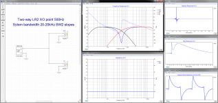
Picture 4-6 is LR3 2-way.
4. Drivers is in same polarity which ruin frq amplitude domain with dip-notch that cancel out at XO point.
5. Tweeter is reversed in polarity and frq amplitude domain is perfect.
6. Woofer is reversed in polarity frq amplitude domain is perfect.
Choose either 5 or 6 as solution but look at step response and decide if woofer shall fire forward or backward on a kickdrum, think i would choose version 5 where tweeter is reversed. SR/IR and square waves is ruined some having IRR phase turn from XO, HARSCH type can improve this still being a IRR type, else go FIR way XO or FIR filter to repair IRR LR2 phaseturn.
Picture 1-3 is LR3 3-way.
1. Drivers is in same polarity which ruin frq amplitude domain with two dip-notches that cancel out at XO points.
2. Mid is reversed in polarity and frq amplitude domain is perfect.
3. Tweeter and woofer is reversed in polarity frq amplitude domain is perfect.
Choose either 2 or 3 as solution but look at step response and decide if woofer shall fire forward or backward on a kickdrum, think i would choose version 2 where mid is reversed. SR/IR and square waves is ruined some having IRR phase turn from XO, HARSCH type can improve this still being a IRR type, else go FIR way XO or FIR filter to repair IRR LR2 phaseturn.
Picture 4-6 is LR3 2-way.
4. Drivers is in same polarity which ruin frq amplitude domain with dip-notch that cancel out at XO point.
5. Tweeter is reversed in polarity and frq amplitude domain is perfect.
6. Woofer is reversed in polarity frq amplitude domain is perfect.
Choose either 5 or 6 as solution but look at step response and decide if woofer shall fire forward or backward on a kickdrum, think i would choose version 5 where tweeter is reversed. SR/IR and square waves is ruined some having IRR phase turn from XO, HARSCH type can improve this still being a IRR type, else go FIR way XO or FIR filter to repair IRR LR2 phaseturn.
Attachments

Last edited:
.....Loopback measurements (if I did them correctly: minijack to dual cinch cable used for measurements, 1 cinch to female minijack dongle, male to male minijack cable to soundcard line in)
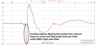
Strange where that filter comes from it looks like a first order BW1 high pass at 1kHz (at fc -3dB amplitude/-45º phase turn and decade -20dB at 10Hz).
Yours at left, mine at right created in Rephase.
(FR was scaled same as yours , but forgot in IR/SR plot scale same X axis)
Attachments
Zonneschimmel,
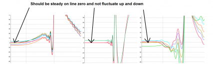
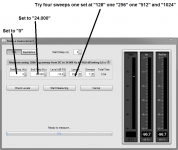
Obeserved fluctuation from measurement to measurement as seen in below picture, often seen this when computer sound device I/O clock is not physical same and as with your setup soundcard output has its own clock then UMIK has its own build in soundcard device and clock and USB bus has its own clock.
What had observed can help here is manual control of sample rate settings and find best performing USB port.
Windows sound system sample rate conversion (SRC) can sometimes be some part of this and if you go to windows sound control and look at UMIK device observe it is locked at 24bit/48kHz and can't be changed, therefor manual set sound device that is used for output so its also at 48kHz 16 or 24 bit, and last thing is in "REW" "Preferences" "Soundcard" tab set also 48kHz.
Also sometimes a particular physical USB port can be more bad or good than another physical USB port on the same hardware platform. One can just try another and see if measurements is improved changing port. A bit more technical one can go to device manager and look for a USB port that have unique its own IRQ and maybe also in device manager set the port to not be steered for power management, need to set device manager tree view right to see the path from device to device and find the right physical port.
Regarding polarity if example woofer move right forward direction and REW show IR/SR reversed then in "REW" "Preferences" "Soundcard" tab set input option "Invert" or per each new measurement basis use "Controls" "Invert impulse".
Attachments
Last edited:
Output is set as default 48kHz 16bit in my Realtek HD Audio manager, if I go to control panel - audio devices the analogue output the default format "when running in shared mode" is set as 48kHz 24bit. REW is also set as 48kHz but I did notice it's using java drivers, should I change that to ASIO?
I was running measurements using a front USB output in the case. I'll run some measurements using the mobo usb.
I was running measurements using a front USB output in the case. I'll run some measurements using the mobo usb.
What operating system is on the PC and laptop? I do remember a post by Bwaslo about the quirks of Windows 8 and above for USB connected mics...
That's a relieve! So no worries there. I'd still like to resolve the strange wiggles you seem to get before each peak. That makes it really hard to determine anything at this stage. We need to know where it comes from i.m.h.o. And we need to remember that the IR is dominated by high frequencies in the way it is presented. But the woofer output so far has not shown the response to change the STEP as it should. It should resemble the prediction made by BYRTT. No need to start combining drivers if it doesn't do it by itself.
In the picture you showed us. The speaker was parked quite close to other stuff around it. Could you slide it forward as to have more clearance around it?
That sort of stuff is what I would do at this stage. And clean up the impulse.
To clean up the wiggles I'd concentrate on the PC, the Nadja and take the 10F run full range. The 10F 8414 should have a pretty clean pulse by itself and should have no wiggles in front of it in a measurement.
Take one step at a time (no pun intended). Do not hurry to the next move until you have the first one covered. One by one would be my advise.
Remember, if you have the Denon inline in HT mode it is connected digitally to the PC. Does it have optical out, like an SPDIF output? That should give an opportunity to connect this setup in a complete digital way. At least I see my TV as a soundcard when connected (actually I see my video driver as that is the one with the HDMI out) and can select it as an audio output device. Worth a shot?
I'll have to check the manual to see if the denon can do that. It would need to get the digital signal from HDMI and output via SPDIF. I have also never used REW with HDMI output...


There is something very wrong when using the usb 3 port, the others are very similar, differences below 30Hz could be due to the cal file not being loaded properly in REW.
There is something very wrong when using the usb 3 port, the others are very similar, differences below 30Hz could be due to the cal file not being loaded properly in REW.
Last edited:
I couldn't get sound out off the optical out of the denon when feeding it stereo through HDMI.
But luckely I had allready dialed in a FAST with only 10F and no tweeter (didn't like it much, couldn't fill the room the sound didn't come loose from the speaker). So I measured that and then pulled out the speaker as far as the cables allow 1m on tweeter axis blankets in place:


It doesn't seem to be room related. Allthough I do have a huge window and a glass wall at the back. The room is about 6mx11m with one 6m side all window and about 7m of one 11m side is glass.
But luckely I had allready dialed in a FAST with only 10F and no tweeter (didn't like it much, couldn't fill the room the sound didn't come loose from the speaker). So I measured that and then pulled out the speaker as far as the cables allow 1m on tweeter axis blankets in place:
It doesn't seem to be room related. Allthough I do have a huge window and a glass wall at the back. The room is about 6mx11m with one 6m side all window and about 7m of one 11m side is glass.
I moved my tower of power next to the pc (that is a shitload of cables to remove and put back again later) Same measurement as before only now I go from PC optical SPDIF out to Najda in, NAD amp (cleaner and easier to hook up)


looks exactly the same

looks exactly the same
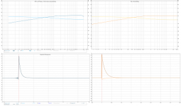
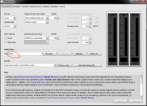
Is it ensured that in soundcard software RealTek or whatever brand that in software control panel no DSP effects is turned on at all.


If your soundcard is calibrated inside REW and lets say ADC have really sharp high pass and low pass filters but DAC hasn't, then response get wrong because we don't use ADC but just DAC to send signal, this can be tested by setting calibration-file to none as below.
Attachments
Are we talking FAST here or single 10F? I'd like to few only one driver playing, preferably the predictable 10F. It's a nice clean driver and no crossovers on it will help view the basic impulse. We are still getting a pré pulse here, unless there's more than one driver that is being exited.
It's only 10F, I can remove the LR2 if you want. It's in a dagger like enclosure with 12.5cm² of opening in the back. Impedance measurements suggest the opening is working a bit like a vent but it was far below crossover point so I didn't bother messing with it yet.
Last edited:
- Home
- Loudspeakers
- Multi-Way
- S. Harsch XO