Have you measured R28 without waveguide ? Just to be sure it's not comming from tweeter itself.
Yes, it's the black curve above.
The smallest CTC distance that is practicable is 6.5in between the RS28 waveguide and the RS180P woofer. That's already with 0.5in cut out of the WG rim. What is the highest crossover frequency I can use given this distance? I calculate a fundamental wavelength of 2070Hz but to avoid inference cancelation aren't we supposed to aim for half this frequency? That would make a 1kHz xo which is way too low for any normal 2 way speaker cabinet. So maybe the xo needs to be below 2kHz is the rule of thumb? I might be just perfect or maybe push down to 1.7kHz just to be safe.
Does anyone have an idea where the 3.7kHz dip is coming from? Or is this normal and to be expected from a waveguide line this?
Unless you plan on using them for a block party, there's nothing wrong with a 1k crossover point with that tweeter in a waveguide. In fact, it's preferable.
That dip seems odd, but so does the rising response of the bare RS28. Are you using too small of a capacitor to protect the tweeter or have DSP enabled? Another possibility is the need for a gasket between the tweeter face plate and waveguide.
If I cross at 1kHz that would be preferable from a sound signature standpoint to keep the XO out of critical 2kHz to 3kHz perception range. My concern was harmonic distortion of tweeter as it falls off below 1kHz and increased HD of mid as it has 1st order slope. An easy way to test is use minidsp to try out various XO points first the build passive XO at best sounding spot. I have putty as sealer between WG and adapter. Maybe foam rubber gasket may be better. 10uF cap may be too small hence the fall off.
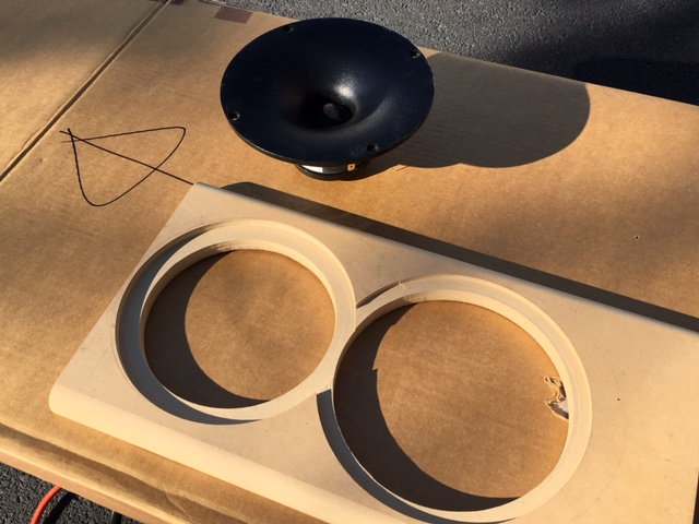


You could have cut the waveguide cutout, mounted the waveguide, then cut the woofer cutout with the waveguide in place.
Good idea Face. Except that this is a redo and I enlarged the home on the tweeter. To remount a centering pin block on backing board would have been too much work. Maybe on next one?
Trim WG to fit woofer bezel
A Dremel tool is your friend. 🙂

I also found that I have to reduce the thickness of the adapter plate by 0.025in (the thckness of the foam gasket in compressed state) to reduce the gap between the WG and the tweeter bezel to hopefully get rid of that pesky 3.7kHz dip. Re-printing will be needed.
A Dremel tool is your friend. 🙂
I also found that I have to reduce the thickness of the adapter plate by 0.025in (the thckness of the foam gasket in compressed state) to reduce the gap between the WG and the tweeter bezel to hopefully get rid of that pesky 3.7kHz dip. Re-printing will be needed.
Attachments
Last edited:
Looks very nice for a hand dremel cut.
Thanks! ABS plastic was first trimmed with a hacksaw to get approximately close. The small 0.5in dia Dremel drum sander tool took it down rest of the way. Cuts like butter so have to be careful not to overdo. I sanded it inside a plastic bag to contain the debris. Worked well in that regard.
I have a general question for those familiar with MDF construction methods. Is using T-nuts on back of baffle with machine bolts/screws, the best way to hold drivers in place? Or using threaded inserts an screws? Certainly wood screws/drywall screws seem out of the question for holding drivers in place. Any recommendations?
Last edited:
For small drivers, I still use either machine or sheetrock screws. Is your baffle at least 1" thick?
I've used threaded inserts in the past. IMO, they aren't worth the effort unless you're dealing with heavy drivers and thin baffles. For example, I'm using standard sheet rock screws to support Dayton UM18s into a 2.5" baffle without any issues... granted, the screws are 2.5" long as well.
I've used threaded inserts in the past. IMO, they aren't worth the effort unless you're dealing with heavy drivers and thin baffles. For example, I'm using standard sheet rock screws to support Dayton UM18s into a 2.5" baffle without any issues... granted, the screws are 2.5" long as well.
I have 3/4in thick MDF baffle and I like 2in or 2.5in long SPAX sheetrock/drywall screws as my mainstay too. I have heard MDF doesn't hold up well to screw thread stress. T-nuts turn it all to normal compressive stress so should be the safest.
t-nuts are great, IF you epoxy/glue them in, otherwise you will find them stripping on you at the most inopportune time, at removal.
My main-stay is coarse thread #6 or #8 black-oxide screws usually 1-1-1/2" long into a 0.75" baffle. If you are needing to screw them in and out a few times, a drop of wood glue, screw them in and then remove, let the glue dry for an hour or two and it solidifies the MDF fibers and have not had a problem removing/reinstalling subwoofers or speakers 5-8 times and still holds strong.
My main-stay is coarse thread #6 or #8 black-oxide screws usually 1-1-1/2" long into a 0.75" baffle. If you are needing to screw them in and out a few times, a drop of wood glue, screw them in and then remove, let the glue dry for an hour or two and it solidifies the MDF fibers and have not had a problem removing/reinstalling subwoofers or speakers 5-8 times and still holds strong.
You can just use wood screws if you don't intend to mount and demount the drivers dozens of times (put a dab of glue in the hole, squeeze it in there with the screw and let it dry without the screw). There are also special MDF or fibreboard screws with bigger thread. I'm using these for mounting 22W and 26W (in baltic birch baffle), they have a pretty big thread. M5 x 30mm Cap Head Wood Screws Black 100 Pcs.
I've used t-nuts only for very big drivers (<10") or for mounting the whole baffle. Be carefull not to tighten too much, with these its very easy to put way to much pressure on the driver basket.
I've used t-nuts only for very big drivers (<10") or for mounting the whole baffle. Be carefull not to tighten too much, with these its very easy to put way to much pressure on the driver basket.
Thanks for the tip on the glue to reinforce the threads. I probably need to remove and reinstall at least 6 times due to working and refining the passive XO. What do you guys use to form an airtight seal between the driver and baffle? I was going to use foam rubber weatherstripping with adhesive on one side. I have thick felt weather stripping too. The waveguide needs to be mounted with rather thick gasket as I made rebate a bit too deep. The foam rubber stripping is ideal thickness for this.
I don't use anything as a seal for drivers anymore. I tried using the wheatherstripping but it's very annoying trying to get it to follow the curve and falls of after 2-3 remounts. It does work better for straight sections.
Passive Radiators
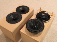
The PR's arrived from PE today. They look nicely made and have a rather thin bezel that will allow them to be surface mounted. Although I will be cutting the holes with a circle jig so I may as well rebate them for a nice finished look. They include a nice built in foam rubber gasket ring that is pre-glued to the bezel for an air tight seal, critical for a good PR operation. There is provision for adding mass via a threaded bolt on the back of the cone/dustcap. The large half-roll rubber surround looks like it has a good amount of linear xmax (8mm specified). The PR's pretty much take up all the space on the back wall of the speaker and finding a place to put the two speaker binding posts is tricky. There is a brace right at the midpoint of the cabinet so can't put it there. I can see how all the PR surface area will really give some nice bass extension to this speaker.
Specs:
http://www.parts-express.com/pedocs/specs/295-498--sd175-pr-spec-sheet.pdf
Attachments
Last edited:
Why not mount them on sides ?
They are the largest in surface and would be most prone to resonating. That way you avoid heavy bracing and you get enough room on the back side for terminals.
They are the largest in surface and would be most prone to resonating. That way you avoid heavy bracing and you get enough room on the back side for terminals.
Last edited:
I thought about that but the side panels would lose a lot of their structural strength with big holes in them. Whereas the back is relatively small area and is braced very close by. Also, I think it looks better on the back and from a sound pressure standpoint, provides more of a dipole radiation pattern which is more uniform. The binding posts are not a big deal.
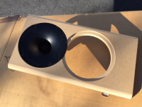
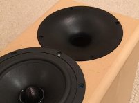
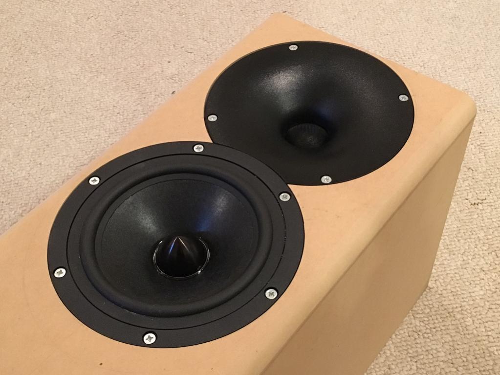
Drivers and WG fit perfectly
I installed the Spax drywall screws after drilling a hole in the MDF and agree it holds pretty well. If I take it on or off I will add glue to the hole as suggested to strengthen threaded fibers. The fit is perfect - not too bad for my first job with router and hole cutting jig. I made little trapezoidal sections of gasket using foam weather stripping to cushion and seal the waveguide against the baffle. Seems to work well. The woofer already had a foam rubber gasket under the bezel from the factory. Also, the new waveguide adapter plate, now 0.025in thinner, fits perfectly and pushes the lip of the waveguide flush with the rim of the tweeter edge. Hopefully this will make that 3.7kHz dip go away.
I installed the Spax drywall screws after drilling a hole in the MDF and agree it holds pretty well. If I take it on or off I will add glue to the hole as suggested to strengthen threaded fibers. The fit is perfect - not too bad for my first job with router and hole cutting jig. I made little trapezoidal sections of gasket using foam weather stripping to cushion and seal the waveguide against the baffle. Seems to work well. The woofer already had a foam rubber gasket under the bezel from the factory. Also, the new waveguide adapter plate, now 0.025in thinner, fits perfectly and pushes the lip of the waveguide flush with the rim of the tweeter edge. Hopefully this will make that 3.7kHz dip go away.
Attachments

- Home
- Loudspeakers
- Multi-Way
- RS28F-RS180P-B80 as Hole Filler 3-way