Thanks Fluid,
Thanks for the link. My point is, this is a quarter century after Peak Consult and Avalon and the like the were doing faceted baffles.
Surely there was science or a method to their madness. I mean triple layer thick baffles then facetting or rounding then finishing them is a lot of labour intensive and costly work. 25 years ago computers were very slow...
You'd think we'd be using CUDA/Nvidia GPUs to be simulating all this (movement of all drivers on the baffle, facets and bezels and roundovers of any arbitrary size, cabinet for any forms and dimensions) in real-time by now... Maybe the industry developed their own software that DIYers don't have access to?
Last edited:
We used to do baffle simulations with a pencil and a hand calculator.. and there was a lot of information, considering, it just took time. I mean, Olson looks to have done his work before calculators. We would also do charts of the amount of diffraction by delay, the amount of diffraction by the angle of incidence relative to a speaker axis, before starting on other axes.
Last edited by a moderator:
For sure there is method, keeping minimal baffle area around each driver and progressing away from the baffle as soon as possible. It is one of the only practical ways to do it so it could easily have been empirically designed. The fact that it also looks good is why it has been so popular.Surely there was science or a method to their madness. I mean triple layer thick baffles then facetting or rounding then finishing them is a lot of labour intensive and costly work. 25 years ago computers were very slow...
The first paper on the Finite Element method was from 1956 so the thoughts behind the process have been around long time before the computer power was available to really make use of it. Even now without a number of simplifications the processing needed is pretty huge. Full 3D mesh sims being particularly demanding.
There are a number of commercial programs that companies may use, Comsol being the most prevalent among those who can afford and make good use of it. They are very good at refining and answering what if questions. There is no mystery or proprietary code needed anymore if it ever existed. Good engineering with a bit of cut, try, measure seems most likely to me.
beautiful cabinets from Peak Consult back in the 90s
Still in business, these the sort of shape?
dave

Thanks for the link. My point is, this is a quarter century after Peak Consult and Avalon and the like the were doing faceted baffles.
My guess as to the how they were doing it, is by experimentation. Numerical analysis was too expensive back in the 1990's. My experience was with structural FEMs, and those FEM codes ran on HP Unix work stations or DEC VAX and Alpha machines, and you needed that kind of horsepower to run structural FEMs. PC's were orders of magnitude less capable than what was needed for simulation. The DEC Alpha was the first 64 bit processor, and it was decades ahead of the first 64 bit Intel processor. I am sure that acoustical BEM code is just as intense and demanding as structural FEMs. Furthermore, there was very little open-source code, which means you were buying or licensing very pricy software. I just don't see a small speaker company buying/leasing that kind of equipment and software back then.
On the other hand, a good engineer can get a lot of useful relationships by testing prototypes. I would guess they built various prototypes and test baffles, took careful disciplined measurements, matched the data up to acoustical physics, and built up some empirical relationships.
You'd think we'd be using CUDA/Nvidia GPUs to be simulating all this (movement of all drivers on the baffle, facets and bezels and roundovers of any arbitrary size, cabinet for any forms and dimensions) in real-time by now... Maybe the industry developed their own software that DIYers don't have access to?
That would certainly be nice. When I stopped being involved in FEMs, the most labor intensive part of the job was building the mesh and handling the boundary conditions. There were auto-mesh features in the software, but it only helped up to a point. Fluid can tell us how long it would take to mesh out a full 3-way speaker with waveguide tweeter... my guess is hours, not minutes. Until that changes, nothing is going to happen in real time... but it is nice to dream 🙂
j.
Making a speaker mesh is much the same, the time it takes depends a lot on your skill and experience with CAD software and how the meshing algorithms work. Making the initial model is more time consuming than solving it but with iterations it swings the other way. What works best to save time is splitting the model into separate parts, because there is rarely a ned to know what a woofer is doing at 15K or what a tweeter is doing at 20Hz. High frequencies take much more time to solve than low ones.When I stopped being involved in FEMs, the most labor intensive part of the job was building the mesh and handling the boundary conditions. There were auto-mesh features in the software, but it only helped up to a point. Fluid can tell us how long it would take to mesh out a full 3-way speaker with waveguide tweeter... my guess is hours, not minutes. Until that changes, nothing is going to happen in real time... but it is nice to dream 🙂

A selection of roundover bits.
1.5" Roundover bits are scary.
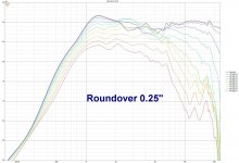
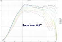
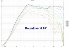
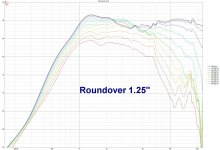
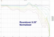
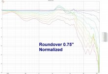
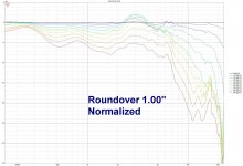
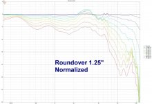
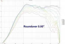
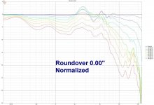
Roundover data,
1.5" Roundover bits are scary.
Roundover data,
Attachments
-
 big roundover bffle.jpg378.9 KB · Views: 248
 -
 big roundover.jpg491.3 KB · Views: 234
 -
 six roundovers.jpg383.1 KB · Views: 233
 -
 RO 0-25.jpg177.3 KB · Views: 229
 -
 RO 0-00.jpg177.9 KB · Views: 213
 -
 RO 0-50.jpg176.5 KB · Views: 200
 -
 RO 0-75.jpg175.5 KB · Views: 198
 -
 RO 1-50.jpg174.1 KB · Views: 216
 -
 RO 1-25.jpg174.7 KB · Views: 217
 -
 RO 1-00.jpg175.4 KB · Views: 221
 -
 RO 0-00n.jpg171.9 KB · Views: 210
 -
 RO 0-25n.jpg171.7 KB · Views: 218
 -
 RO 0-50n.jpg170.2 KB · Views: 210
 -
 RO 0-75n.jpg169.6 KB · Views: 198
 -
 RO 1-00n.jpg168.7 KB · Views: 213
 -
 RO 1-25n.jpg168.2 KB · Views: 218
 -
 RO 1-50n.jpg167.8 KB · Views: 252
Last edited:
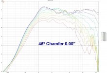
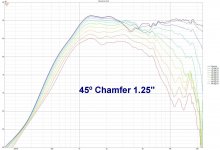
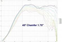
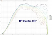
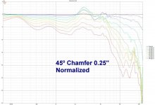
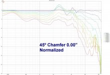
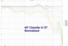
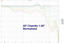
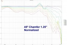
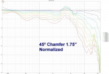
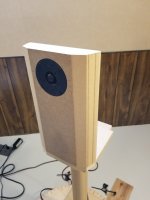
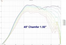
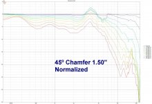
45º Chamfer data,
Attachments
-
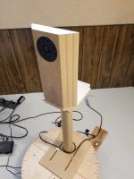 20220321_142056.jpg336.2 KB · Views: 201
 -
 CH 0-25.jpg178.1 KB · Views: 194
 -
 CH 0-00.jpg180.1 KB · Views: 166
 -
 CH 0-50.jpg176.8 KB · Views: 158
 -
 CH 0-75.jpg177.2 KB · Views: 155
 -
 CH 1-25.jpg176.2 KB · Views: 162
 -
 CH 1-00.jpg176.5 KB · Views: 156
 -
 CH 1-75.jpg176.8 KB · Views: 167
 -
 CH 1-50.jpg176.5 KB · Views: 175
 -
 CH 2-00.jpg176.3 KB · Views: 200
 -
 CH 0-25n.jpg171.6 KB · Views: 175
 -
 CH 0-00n.jpg174.1 KB · Views: 176
 -
 CH 0-50n.jpg171.9 KB · Views: 170
 -
 CH 0-75n.jpg169.6 KB · Views: 154
 -
 CH 1-00n.jpg170.9 KB · Views: 164
 -
 CH 1-25n.jpg170.6 KB · Views: 154
 -
 CH 1-50n.jpg170.5 KB · Views: 167
 -
 CH 1-75n.jpg170.4 KB · Views: 162
 -
 CH 2-00n.jpg170.9 KB · Views: 188
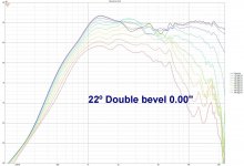
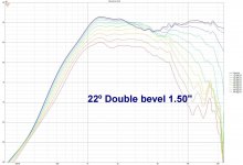
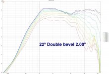
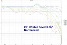
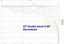
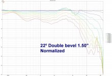
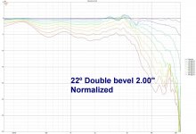
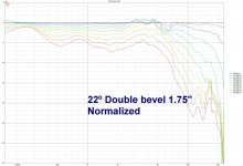
Double 22.5º Bevel data,
Attachments
-
 20220321_141832.jpg222.3 KB · Views: 191
 -
 CH22 0-00.jpg180.5 KB · Views: 177
 -
 CH22 1-00.jpg175.8 KB · Views: 145
 -
 CH22 0-75.jpg177.8 KB · Views: 152
 -
 CH22 1-25.jpg175.3 KB · Views: 140
 -
 CH22 1-50.jpg174.9 KB · Views: 151
 -
 CH22 2-00.jpg175.6 KB · Views: 142
 -
 CH22 1-75.jpg175.3 KB · Views: 166
 -
 CH22 0-75n.jpg172.2 KB · Views: 151
 -
 CH22 0-00n.jpg174.5 KB · Views: 150
 -
 CH22 1-25n.jpg168.3 KB · Views: 156
 -
 CH22 1-00n.jpg168.3 KB · Views: 140
 -
 CH22 1-50n.jpg168.4 KB · Views: 156
 -
 CH22 2-00n.jpg169 KB · Views: 160
 -
 CH22 1-75n.jpg169.3 KB · Views: 181
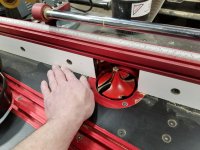
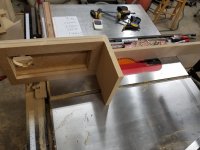
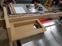
Here is how I did the double 22.5º bevel, Making a double 22.5º bevel edge on corner of speaker boxes.
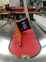
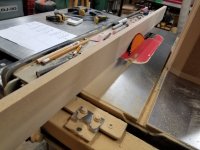
Because you will need to bury your blade into your table saw fence, attach a sacrificial 3/4" MDF fence with double sided carpet tape. Conceivably you could do it with blade tilting away from the fence, not into it, but it would require two fence settings and this way ensures the cut is symmetrical on both faces.
Had to do some right angle math in order to calculate the fence setting for various "radius's" (b on the sheet) and account for the sacrificial fence and the blade width. This hinges on you having a scale on the left side of the blade with a accurate reading cursor on that side.
Set the blade to 22.5º (or the complimentary 67.5º), set the fence to the desired chamfer size, raise the blade until both sides of the blade are cutting into the sacrificial fence, make four cuts and you have a perfect symmetrical 22.5º bevel on the face and the side of the box!
Attachments

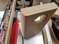
And here is what I was most interested in,
How do these four compare on a 9" baffle,
It looks like 45º edge bevels are not as good as roundovers and double 22.5º bevels are the functional equivalent of a roundover.
How do these four compare on a 9" baffle,
It looks like 45º edge bevels are not as good as roundovers and double 22.5º bevels are the functional equivalent of a roundover.
Attachments


Nice work! You may have just saved me a lot of time! Post your baffle dimensions, I want to see if I can replicate this in ABEC if you don't mind.
I think roundover looks the best, but as I've noticed in past measurements, they behave as a slightly wider baffle than a chamfer. My issue is with a waveguide, the roundover looks smoother, but is lower in frequency where my waveguide doesn't have much pattern control. So I'll have to do my own tests with a box I just built anyway it appears.
I think roundover looks the best, but as I've noticed in past measurements, they behave as a slightly wider baffle than a chamfer. My issue is with a waveguide, the roundover looks smoother, but is lower in frequency where my waveguide doesn't have much pattern control. So I'll have to do my own tests with a box I just built anyway it appears.
It is really hard to make a totally even comparison between them particularly the roundover and the chamfer as it changes the baffle geometry. In practical terms the double bevel actually spreads the lower diffraction peak more, it makes the effective baffle smaller which is a good thing and smooths the transition more nicely like a roundover. Applying that at an angle would be effective much like kimmo's preferred rounded facets.And here is what I was most interested in,
How do these four compare on a 9" baffle,
It looks like 45º edge bevels are not as good as roundovers and double 22.5º bevels are the functional equivalent of a roundover.
The data is interesting, but i suspect things will be different if you add sides to the box.
dave
dave
DaveFred,
When the notes say "Double bevel, 2 inch", am I to understand that the baffle is 2 inch think?"
Am I understanding it correctly?
When the notes say "Double bevel, 2 inch", am I to understand that the baffle is 2 inch think?"
Am I understanding it correctly?
Also confirms what I've read previously- small round-overs are not worth doing. Anything 3/4" or less is really not worth it. Merely an aesthetic effect.
If you're going to do a round-over, do a 1.5" roundover.
My smallest round-over bit is 1". Maybe it's time to find the biggest round-over bit that will fit my router...
If you're going to do a round-over, do a 1.5" roundover.
My smallest round-over bit is 1". Maybe it's time to find the biggest round-over bit that will fit my router...
- Home
- Loudspeakers
- Multi-Way
- Roundover vs. 45º Chamfer vs. Double 22.5º Chamfer edge treatments for tweeter diffraction.