As I as reading this I am playing with a signal generator lol. I can hear the loss of output drop under the anticipated 140ish area....Good example.. akabak doesn't show all the things that matter, but you (we) will 'find' good results if that is what you are 'looking for'. Excessive reliance on the simulator exposes one to potential obsession.
So I am kind of getting the idea of wanting to place what is essentially a "filter" (can I say that?) strategically right near an Xo point... or above the majority of the passband? Personally I want as much efficiency and direct energy as I can create which is why I chose the easy way out ie extra wide baffle...
@fluid I think I conceive properly the directivity shift that is considered unoptimal.
I always thought that it was a benefit....You could only judge some things with a grain of salt, that quickly but if one was super familiar with reference material then that would provide a set up for the best judgment.....In particular if you sought out a recording that was engineered as neutral as possible... I sampled content just the other day that had a particular voicing that was not neutral... even after all of that....I still trust measurements over ears...Ears are like eyes and have balancing mechanism...which is funny to say because its within the first few minutes of listening that your ears the most fresh and neutral.I’m friends with music and studio professionals (ie. working musicians as a primary job) and some of them have amazing ears-
I can hear the room vs direct energy pretty good though...thats probably a big part of it concerning baffle design....
I wish it could be explained simply in a one line reply but it can't, at least not by me. Each individual case needs to be looked at and simulated or measured to see how the whole interacts. Trying to come up with rules of thumb, reducing the data to be more manageable is understandable but will not always give the correct answer when it is applied differently.Now theres the meat... can you please elaborate?
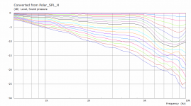
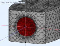
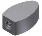
Here is an example of something I consider to be close to optimal for this driver size in a finite baffle from @wesayso. It needed a chamfer in front of the driver to pull the whole thing together. Without that chamfer the overall directivity was not as good even though the enclosure shape was the same.
https://www.diyaudio.com/community/...ver-full-range-line-array.242171/post-6523730
When the frequency range is restricted to leave out the driver beaming there is not much to complain about.
Attachments

In the post linked to above wesayo and I both created different speaker cabinets without any use of a simulator, mine was simpler and more straight forward, his more elaborate. I always had trouble setting the upper mid balance, always a compromise. Much later on I simulated both to see what the differences were, low and behold my cabinet creates differences in the on and off axis sound around that area.Good example.. akabak doesn't show all the things that matter, but you (we) will 'find' good results if that is what you are 'looking for'. Excessive reliance on the simulator exposes one to potential obsession.
Since then I have tried to learn the lessons of what a simulator can tell me before making the mistake.
It is a useful tool to see what you might get and if there is potential for improvement, just like a measurement mic is a handy tool to get an idea of what you actually got.
When simulations are accurate enough to be relied upon their use is beneficial, KEF, B&W, Harman etc. use them because it benefits their products. With any powerful tool there is the potential become bogged down in minutiae just like having a high resolution measuring system could lead someone to try and remove every last bump and dip.
This thread contains great data and experimentation and only reinforces to me how accurate a full 3D simulation can be.
Your post sounds condescending, it may not have been your intention but I am a cynic so that is how I read it.
Well, I dunno, I don't think Allen meant anything by it. Sometimes we say something for humorous effect, sometimes we say something flippant because, well, aren't we all a little obsessed, with audio? By definition, if we're here, I think we all are. Allen too.
I mean, the 99% of the population couldn't care less about what speakers they have (or don't have), and here we are analyzing jiggly lines on and off axis. That may or may not have an effect...
I mean, the 99% of the population couldn't care less about what speakers they have (or don't have), and here we are analyzing jiggly lines on and off axis. That may or may not have an effect...
an original Harman Kardon.
2 channels, 4 amps, DSP and dual passive radiators.
Simulated and prototyped to nth degree before mass production, for sure.
Last edited:
Yes I'm afraid so.Allen too.
While designing the types of speaker I prefer, the compromises are often so close that I need to find the limits on dimensions/angles/frequencies/performance and audibility, or it will make something else suffer. It's fun to optimise the stuffing out of one component if you understand the limitations, but often counter-productive.
Know what does and doesn't matter.
I'm starting to see your point but I think I just confused myself....Is bafflestep an unavoidable trait?
...
Infinite baffle has no edge to interact with, but then you say here "path length along the baffle just "smears" the direct sound" So infinite baffle has max direct energy smear.....This is bad? or just different.
Hi, many questions, sorry I don't have time currently to write elaborate reply and there is no short answers 😀 You seem to be on thought process and need some more thinking before all comes together. For example "the resonant note that occurs right before the baffle looses directivity" you mention seems to be referred as "main diffraction hump" by others, at least lots of texts appear as you search by that. I've just thought about the diffraction hump for few evenings and wrote long thought process spanning multiple posts on another thread which should help you a lot on your thought process I think, at least we would probably get more on same page with diffraction if nothing else, if you happen to read it all through 😀OK I think I am seeing the picture now....and its pointing back to keeping bafflestep away from some arbitrary point.
looking at post 70, my thoughts are" Oh, edge treatment can mitigate baffle step....but at a very wide baffle, this would be impractical due to the size of the edge treatment needed to be effective there?" Maybe I said that wrong....Edge treatment can remove the resonant note that occurs right before the baffle looses directivity is what I mean.
I hope I didn't miss anything.... It sounds like to me, a very wide baffle is a version of optimal...at 143hz there are no ripples to worry about and it is so deep into the room territory that would require eq anyway....also creating as much direct energy as I can.
Key point is that it is all relative to wavelength and physical object size like demonstrated on the previous post. In addition you need to think what is relevant, how hearing system works and how speaker system works with room in order to manipulate and manage the diffraction / bafflestep at the speaker construct so that their contribution does not hamper the performance of your system and doesn't make your life too hard designing other aspects of your system. Hope it helps. Feel free to ask more, will try to explain if I can. There is a lot of stuff on the web for all this and you should be able to find answers to any questions you have by searching around.
To camplo,
Please study basics of sound wave radiation and dispersion! The challenge comes from wide range of wavelengths needed for audio/music.
https://www.trueaudio.com/st_diff1.htm

Baffle loss/step happens at wavelengths longer than baffle's shortest dimension - wavefront bends over the baffle/box and thus on-axis sound pressure level (spl) attenuates (max -6dB)
Edge diffraction happens at shorter wavelenths than baffle's shortest dimension - the bending wave at the edge creates a secondary radiation source that starts to interfere with the original soundwave. This interference creates undulations in spl response - different on- and off-axis (typically +/- 2dB)
These effects have maximal effect in a round baffle, where distance from the source to the edge is constant. Typical speaker baffles/boxes are rectangular which distributes both baffle loss and diffraction frequencies.
The Edge is a simple and free simulation to study these phenomenoms http://www.tolvan.com/edge/help.htm

Please study basics of sound wave radiation and dispersion! The challenge comes from wide range of wavelengths needed for audio/music.
https://www.trueaudio.com/st_diff1.htm
Baffle loss/step happens at wavelengths longer than baffle's shortest dimension - wavefront bends over the baffle/box and thus on-axis sound pressure level (spl) attenuates (max -6dB)
Edge diffraction happens at shorter wavelenths than baffle's shortest dimension - the bending wave at the edge creates a secondary radiation source that starts to interfere with the original soundwave. This interference creates undulations in spl response - different on- and off-axis (typically +/- 2dB)
These effects have maximal effect in a round baffle, where distance from the source to the edge is constant. Typical speaker baffles/boxes are rectangular which distributes both baffle loss and diffraction frequencies.
The Edge is a simple and free simulation to study these phenomenoms http://www.tolvan.com/edge/help.htm
Last edited:
To camplo,
Please study basics of sound wave radiation and dispersion! The challenge comes from wide range of wavelengths needed for audio/music.
View attachment 1037701View attachment 1037707
I am familiar with this material, its just for my particular situation I am speaking on. 15" woofer with a 32" wide baffle...the woofer is slightly off centered
Its not like we aren't going to use room correction that low...Its just another bump in the road that may or may not need to be ironed with eq, as the room sees it.... As well, there are no diffraction peaks and dips above baffle step...with a 32" wide baffle...Its just not coming into how my vertical polar is in play...as well, that we are looking at a 2db hump lol
I think this has been my point the whole time as I am only referring to where my situation fits into the greater scheme of things.
As Fluid said, the change in directivity is what he's looking at...I see it as not a win or a loss for me....I can either keep the highest amount of directivity well into the room mode territory with con of a directivity change within the at ~141hz passband or I can make baffle as narrow as I can say 17" and the baffle looses directivity at ~265hz....The edge diffraction effects get more intense as you shorten the baffle length....and less intense as we widen the baffle...
I forget that I have the tools to simulate my situation on some level, forgive me for being so helpless. Heres a my 15" on the 32" baffle, perfectly centered....Normalized sim by Vituix
If I am correct, this isn't as detailed as possible because the side walls are not simulated? I don't know.
My vertical represents the shortest baffle you might find on a 15"
I guess this is more a result of the directivity of the 15" not letting the edge interaction happen.
THis is just looking at the mid enclosure alone....since diffraction will happen at every other object the source waves encounter in the area...like the sub box for example.
Last edited:
I want to say that an extra wide baffle is another Form of optimal.....I am trying to figure out how this isn't true.... Looking what I can sim....I'd say that I am right....but maybe there or more details with an akabak sim.
Just because I want to say that, doesn't mean its correct...I was chasing as much direct energy as I could and somehow I landed here. Optimal for me isn't optimal for the next guy....still I want to see the bad...I don't see it in these sims.
Above grammar correction; "Its just now coming into view, how my vertical polar is in play...as well, that we are looking at a 2db hump lol"
camplo, what is the passband of your 15" driver? And yes, it has very little edge diffractions, so edge contour is practically irrelevant.
Baffle loss/step is unavoidable, and depending on how it matches passband, it can or must be compensated somehow or "integrated" in acoustic crossover highpass slope.
"I can either keep the highest amount of directivity well into the room mode territory with con of a directivity change within the at ~141hz passband or I can make baffle as narrow as I can say 17" and the baffle looses directivity at ~265hz....The edge diffraction effects get more intense as you shorten the baffle length....and less intense as we widen the baffle..."
A 15" woofer in any baffle (except open/dipole) has practically no directivity in room mode territory (below 200Hz)! Around 100-400Hz happen most of first reflections from the floor, ceiling and side walls, but at angles where directivity effect is also small.
I just don't understand what you are asking about in this thread, which is about edge diffractions with different edge contour.
Passband

Directivity

The loss in directivity manifest as a loss of efficiency. I would have to Room correct my speaker to give a more conclusive opinion but with my anechoic response voiced neutrally, I can hear a change at 140hz sitting at about 45" away....below 140hz I hear the room more....but that is not very scientific is it lol...Just consider that there are resonant notes below 140hz and it sounds like it comes from the room as the resonant notes I hear above 140hz sound like its coming from the speaker. I would have to go back and experiment again, to be more specific about where that happened but its completely unscientific so take with a grain of salt.
I just realized maybe you meant passband....literally, as in intended passband within the system....low pass somewhere between 300-600....High pass at 65hz
"I just don't understand what you are asking about in this thread, which is about edge diffractions with different edge contour." _ as I said, I am just trying to figure out where my design fits in, according to this topic. Completely missing the part focusing on tweeter 🤔 turning negatives into positives.... Maybe I am showing another answer to the problem, since dynamic tweeters will not interact with a 32" wide baffle....and the frequencies that do interact, need no edge treatment... and then a horn/waveguide, which should come with an optimal mouth edge contour, if implemented into a flat baffle...can benefit from the same traits.
thus it is, an unlisted solution of sorts?
Think;
Directivity
The loss in directivity manifest as a loss of efficiency. I would have to Room correct my speaker to give a more conclusive opinion but with my anechoic response voiced neutrally, I can hear a change at 140hz sitting at about 45" away....below 140hz I hear the room more....but that is not very scientific is it lol...Just consider that there are resonant notes below 140hz and it sounds like it comes from the room as the resonant notes I hear above 140hz sound like its coming from the speaker. I would have to go back and experiment again, to be more specific about where that happened but its completely unscientific so take with a grain of salt.
I just realized maybe you meant passband....literally, as in intended passband within the system....low pass somewhere between 300-600....High pass at 65hz
"I just don't understand what you are asking about in this thread, which is about edge diffractions with different edge contour." _ as I said, I am just trying to figure out where my design fits in, according to this topic. Completely missing the part focusing on tweeter 🤔 turning negatives into positives.... Maybe I am showing another answer to the problem, since dynamic tweeters will not interact with a 32" wide baffle....and the frequencies that do interact, need no edge treatment... and then a horn/waveguide, which should come with an optimal mouth edge contour, if implemented into a flat baffle...can benefit from the same traits.
thus it is, an unlisted solution of sorts?
Think;
Roundover vs. 45º Chamfer vs. Double 22.5º Chamfer edge vs Extra wide baffle for tweeter diffraction
Last edited:
The two comparison images show the point I am trying to explain. The vertical shows a smoother response overall, there the off axis response continues to drop as the angle increases. That is not the case with the wider baffle. The wider spread of the curves in the vertical indicates that there is more energy directed to the front with the narrower baffle dimension.As Fluid said, the change in directivity is what he's looking at...I see it as not a win or a loss for me....I can either keep the highest amount of directivity well into the room mode territory with con of a directivity change within the at ~141hz passband or I can make baffle as narrow as I can say 17" and the baffle looses directivity at ~265hz....The edge diffraction effects get more intense as you shorten the baffle length....and less intense as we widen the baffle...
It is not totally accurate particularly at low frequencies as without the depth the full shape of the step is not accounted for and the impact this has on the directivity is missing.If I am correct, this isn't as detailed as possible because the side walls are not simulated? I don't know
More direct energy in comparison to the off axis...but not more direct energy in totalThe wider spread of the curves in the vertical indicates that there is more energy directed to the front with the narrower baffle dimension.
17x17
32x32
32wX17h
Perhaps you have your own definition of direct energy, because a speaker that is more forward directional puts out more direct energy by common definition. I would not choose the super wide baffle for all the reasons I have stated (and graphs shown) but you have already made your choice and it's not a bad one.More direct energy in comparison to the off axis...but not more direct energy in total
I think I am saying it right??? When we look on axis....as we see in the graphs above....increasing baffle width increases output, the extra output is more direct energy.....The off axis performance looks that way it does because the with wider baffle its like the source is wider....with the smaller baffle the source is smaller......
if we ever get a simulation in akabak it will be obvious.... and the direct energy will extend further out into space, away from the baffle... with the wider baffle than it will with the smaller baffle, all other things equal....
A smaller baffle creates less off axis energy....not more direct energy....a larger baffle creates more off axis energy....not less direct energy.
It will look something like this...

The greenish is the wider baffle..
The Blue is the skinnier baffle...
Both are representing Direct energy.
The baffle sends more energy forward but not where there is no baffle of course...making the skinnier baffle have a more narrow polar but less direct energy..... hence the higher output directly on axis....and off axis. I am not going to say the shapes are dead accurate...just the concept...especially considering this is frequency specific and the shape will change with it. Looking at just the on axis.... This is why the output is higher in the areas that it is, in the above examples....and what the off axis does not fall off as fast.
17x17 with my woofer

32x32 with my woofer

if we ever get a simulation in akabak it will be obvious.... and the direct energy will extend further out into space, away from the baffle... with the wider baffle than it will with the smaller baffle, all other things equal....
A smaller baffle creates less off axis energy....not more direct energy....a larger baffle creates more off axis energy....not less direct energy.
It will look something like this...
The greenish is the wider baffle..
The Blue is the skinnier baffle...
Both are representing Direct energy.
The baffle sends more energy forward but not where there is no baffle of course...making the skinnier baffle have a more narrow polar but less direct energy..... hence the higher output directly on axis....and off axis. I am not going to say the shapes are dead accurate...just the concept...especially considering this is frequency specific and the shape will change with it. Looking at just the on axis.... This is why the output is higher in the areas that it is, in the above examples....and what the off axis does not fall off as fast.
17x17 with my woofer
32x32 with my woofer
Last edited:
I accidently left the filters on, let me try that again...
32x32

17x17

In the above...The yellow, that is the evidence of more direct energy....the natural roll off of the driver at 50hz is seen.

My first Gif eva lol....This is what I mean by the source appearing wider....and even like a large driver, directivity increases. This directivity can be seen in the upper graphs in the yellow. Its wider, yet it moves more directionally...Similar would be a horizontal array of drivers in my case of the short and extra wide...
and finally mine
32wX17h

An akabak sim would be , more revealing. its like the "source" appears wider (larger)...but the directivity is more narrow. The above graphs say that the wider baffle is more directional and has more direct energy
32x32
17x17
In the above...The yellow, that is the evidence of more direct energy....the natural roll off of the driver at 50hz is seen.
My first Gif eva lol....This is what I mean by the source appearing wider....and even like a large driver, directivity increases. This directivity can be seen in the upper graphs in the yellow. Its wider, yet it moves more directionally...Similar would be a horizontal array of drivers in my case of the short and extra wide...
and finally mine
32wX17h
An akabak sim would be , more revealing. its like the "source" appears wider (larger)...but the directivity is more narrow. The above graphs say that the wider baffle is more directional and has more direct energy
Last edited:
Here is the catch, if you were looking the on-axis frequency response curve writing this it is true, the line rises with frequency on the baffle step, which in turn gets lower in frequency as the baffle gets bigger, true more sound forward as baffle gets bigger. But wider baffle doesn't make your source wider, source is still the same driver on the baffle and the baffle edge turns the sound that originated from the transducer and travelled across the baffle to the edge making secondary sound source at the edge due to diffraction. But the secondary sound source polarity is flipped (towards listening position, and back where the wave came from). And this is of course delayed from the direct sound depending where you observe at and how long it travelled along the baffle before diffraction. As you make the baffle bigger, the baffle step gets lower in frequency as lower frequencies get projected forward instead of wrapping around but also all of this edge diffraction has more delay to it showing interference lower in frequency. This all means that all you do while enlargening baffle is drag all the bafflestep + diffraction and issues lower in frequency, later in time.I think I am saying it right??? When we look on axis....as we see in the graphs above....increasing baffle width increases output, the extra output is more direct energy.....The off axis performance looks that way it does because the with wider baffle its like the source is wider....with the smaller baffle the source is smaller......
Your analogy is kind of right, "the source" is now bigger with bigger baffle, but it doesn't represent equally big transducer, it is the same transducer + various amounts of sound at various delays dragging behind and at opposite polarity if inspected on-axis. This of course adds more energy to front (or to any direction) at certain wavelengths, where there is constructive interference, but it also creates less energy where there is destructive interference. When the wavelength is longer than size of the baffle, below bafflestep, where the system radiates all around and has lost its directivity completely, all the sound from the transducer comes as one toward the listener, without all the hash reflected from the edges dragging behind.
All this is kind of semantics, if you just look at the frequency response plots and see on dramatic wiggle happening, in other words get smooth graphs for the whole loudspeaker system, all should be fine. Here is diffraction tool sim with approximation of the subwoofer enclosure included, I don't know the exact dimensions so it is probably off some. If you look at it there is some wavy lines on the pass band <600Hz, but the more severe looking thinks happen >600Hz. If you made the baffle bigger but keep the transducer same, all these trends in the graphs move lower in frequency, and if you scale the baffle down keeping the transducer the same then all of it moves up, farther outside of the pass band.

Instead of making the baffle wider one should make the transducer bigger and baffle smaller in order to get maximal output and bandwidth out of the transducer, below frequencies where diffraction is an issue. Think about it a while 🙂 Unfortunately 15" is about the biggest driver one would want to use for mid range duty so multiple drivers would be required, which might just more issues. You can utilize the baffle size as you like, but if you think it through minimal baffle + as big transducer as needed to get the "baffle step" down where one wants it is the key for problem free great "direct energy", opposite of what you propose.
Here is new analogy to think about it: think about 6" driver on 32" inch baffle and compare it to 32" driver on 32" inch baffle. Both would have same bafflestep, but the 32" driver would not have any diffraction ripple because it starts to beam right above the baffle step (only the huge main diffraction hump would be there). The 6" driver would have diffraction ripple above the baffle step up to 6" wavelength. Now think which of these would have more displacement and SPL capability at low frequencies, the 6" driver or the 32" one?😀 Which one has less diffraction problems?


Your system response looks fine from the simple baffle simulation for the intended band pass. It could look a bit better from diffraction point of view if the construct was smaller, or had huge roundovers. But as said, it seems to be just fine and practical like it is for what it is. Although for home use I would just use a lot smaller system, because big size comes from big SPL capability which really is not needed and it comes with issues like this, if it is issue at all. It is an issue for the forums at least, and for us to wonder 🙂
Last edited:
camplo, I am afraid that I don't understand what you are trying to tell, sorry.
You talk about direct energy, but you must specify what that means. Seems to me that you don't mean on-axis (0deg) spl, but what?
1) We must assume that in a sim and in this discussion a radiator vibrates at fixed voltage and excursion and sends fixed total amount of energy. It may be virtual/ideal with flat spl response or a real unit with it's own spl variations that we must normalize for comparison.
2) how this energy gets distributed (spreads) when soundwaves propagate in air out from source in all directions, is what we want to know
3) we want to know how distribution of soundwaves variates with different frequencies (audio band 20 - 20 000Hz)
To study 2) and 3) ie. "spread of energy" we measure (or simulate) sound pressure level (dB) at many points around the source.
With wide distribution, the on-axis spl is lower than with narrow distribution. This is the basic by which spl around a single radiator varies and we can make graphic presentations. Multiple sources will have even more interferences so simulation gets more complicated.
I am very poor in mathematics, I don't understand the formulas that are behind all this. But I have learned to understand graphic presentations. Fortunately in this millenium we have efficient computers and freeware measurement programs, and we can make private tests like OP in this thread. A more sophisticated system is eg. Klippel NFS which is used by eg. Erin Hardison and Amir of ASR forum. Studying those measurements and graphics and comparing results to different speaker constructions is very interesting and educative.
https://www.erinsaudiocorner.com/loudspeakers/
And then - when we listen to a speaker in a room, modes and reflections are the main cause of spl variations we hear or measure when playing sine sweeps! I must put my one ear to only about 20cm to the speaker to hear the dipole cancellation effect.
Last edited:
Maybe I should stick to using visuals huh lol...Thanks for the responses....
When we look at a horn....with the same type of graphs....we only see the direct energy.....Just because the baffle isn't in the shape of a tractrix curve, should not stop us from calling the reflective energy from the front baffle direct energy. The timings are so close, its all good.
Direct energy is essentially all the energy you will see in an anechoic chart, like above. If one were to be anal, we could say that only the anechoic response of the transducer only, is the direct energy....but thats not fair, if we aren't going to do that with horns and waveguides, why do it with the front baffle, they are essentially the same thing.
It is correct to say that direct energy exist from the loudspeaker system, baffle included in an anechoic view....indirect energy is the reflections from the room
The radiator, couples with the horn/waveguide walls, no less, the radiator couples with the front baffle....if it is there to be coupled with. The front baffle is a waveguide...just not a very directional one...still more directional than a smaller front baffle
Maybe I should stick with waveguide analogy instead of horn lol
"constructive interference" yes this is what waveguides and horns have.........I think lol! Pretty sure lol
I might should have used constructive interference instead of the word coupling...
Last edited:
- Home
- Loudspeakers
- Multi-Way
- Roundover vs. 45º Chamfer vs. Double 22.5º Chamfer edge treatments for tweeter diffraction.