Well, at least freestanding waveguide with good profile and round over seem to have very little diffraction so no need to resort to beaming. Just use round overs to reduce diffraction for your source. And you gotta remember the next transducer on a multiway speaker diffracts the other one, woofer diffracts the tweeter if they are next to each other on same baffle since both play at same frequency at crossover and one of the transducers cannot be made small enough not to, exception would be to use some fullrange driver + woofer system and crossover way below either diameter. Also your midwoofer output, even if on a sphere, would diffract on the horn which you need to bring close by. This is splitting hairs though, just make a system and if it is bad then figure out what makes it bad, might not be diffraction or if it is you know exactly what to do with the next system, address diffraction better.
Last edited:

This is in agreement with my statement that not all indirect energy is bad.
Horns no less can be made without diffraction and the indirect/direct also explains why a beaming horn/waveguide has a sharper IR.
Horns no less can be made without diffraction and the indirect/direct also explains why a beaming horn/waveguide has a sharper IR.
Please go and have a sleep 😀 I don't know what is sharp IR, I guess nice IR is made with system that has wide enough bandwidth of smooth frequency response without excess group delay, no reflections or delays or resonances, this is something I haven't been into yet. Beaming would reduce the reflection part I guess but there could be resonances for example, noise, or microphone 1" off to miss the beaming kHz completely making a dull IR 😀
Not all indirect energy is bad, we have them in the room and anechoic chambers are said to sound unnatural, so not all indirect sound is bad. But as it is all "analog" and physical objects in room there is no possibility to have strictly direct energy, only thing one can do is suppress problems enough not to be audible anymore, but there is no need to go any further in order to leave marginal to resolve other compromises, mind the trade-offs.
Not all indirect energy is bad, we have them in the room and anechoic chambers are said to sound unnatural, so not all indirect sound is bad. But as it is all "analog" and physical objects in room there is no possibility to have strictly direct energy, only thing one can do is suppress problems enough not to be audible anymore, but there is no need to go any further in order to leave marginal to resolve other compromises, mind the trade-offs.
Last edited:
The funny thing is that in this case, 65-400Hz (below Schröder) range the room pretty much sums up the on- and off-axis sound energy. Then add boundary gain and reflections messing it all up... So the difference will be hard to hear? And I suppose there will be some BS eq anyway in the design.
Yes. I am skeptical that there is much real world benefit, in most rooms, in trying to manage directivity below 400 Hz.
Wide baffle pushes 2π to 4π tansition down to the point where the wall behind becomes part of the “baffle” and effectly moves any BS down into the room dominant region, or mostly obliviate it.
Gotta get the new midTweeters in to these and get n amp back before moving them upstairs.
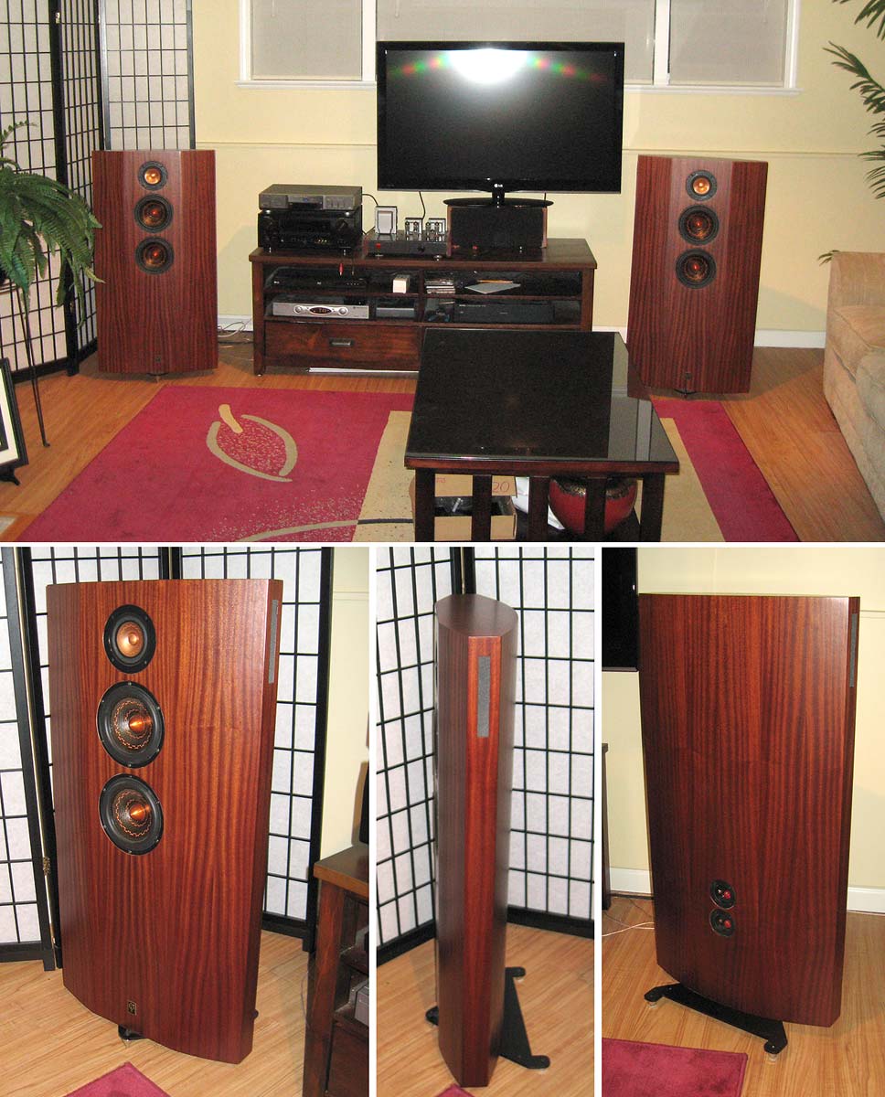
(sorry, 2nd time i have poste dthis pic here), but it does have a wide baffle, and a “double 30/45° bevel" [turned into a smooth curve]). At the highest frequencies dispersion of the midTweeter minimizes higher frequency edge diffraction.
dave
Gotta get the new midTweeters in to these and get n amp back before moving them upstairs.
(sorry, 2nd time i have poste dthis pic here), but it does have a wide baffle, and a “double 30/45° bevel" [turned into a smooth curve]). At the highest frequencies dispersion of the midTweeter minimizes higher frequency edge diffraction.
dave
I said the wider baffle put out more frontal hemisphere sound.
As in the baffle widens the lower the frequecies thst will be radiating into 2∏ stereradians.
dave.
Found it!
1.1.2.5. Reverberant field
The reverberant field of a source is defined as that part of the sound field radiated by a source which has experienced at least one reflection from a boundary of the room or enclosure containing the source.
So I am wrong...but now I will say that horns and waveguides produce a mix of direct and indirect sound since theres at least one reflection unless it beams out of the horn/waveguide... A horn/waveguide is an enclosure containing a source
1.1.2.2. Near field
The near field of a source is the region close to a source where the sound pressure and acoustic particle velocity are not in phase. In this region the sound field does not decrease by 6 dB each time the distance from the source is increased (as it does in the far field). The near field is limited to a distance from the source equal to about a wavelength of sound or equal to three times the largest dimension of the sound source (whichever is the larger).
ok then....can I argue that a larger baffle extends the nearfield??? Since the "source" (always a mixture of direct and indirect sound, unless beaming or baffleless) is larger, when the baffle/horn/waveguide is larger....actually sounds legit
i feel like Ive learned things 😬
waveguides and horns (and woofers on baffles) direct reverberant energy...I mean I know that but I personally would not of thought to classify its output as a mix of direct field and reverberant field... I always thought the "reverberant field" came from the room only.... the more you know😅
The source seems to be a WHO paper about noise... https://www.who.int/occupational_health/publications/noise1.pdf
camplo (applies to all of us), please inform us about the source of information! Discussion without common definitions is fruitless and frustrating.
Toole's book is a very good reference (that I don't own) It is mostly based on definitions used in IEC/ISO etc. Nowdays we see mostly these
- synopsis https://www.harman.com/documents/AudioScience_0.pdf
Toole's book is a very good reference (that I don't own) It is mostly based on definitions used in IEC/ISO etc
1.1.2. Sound Field Definitions (see ISO 12001)
https://www.who.int/occupational_health/publications/noise1.pdf
I have tried to explain it but it is complicated and not necessarily intuitive. How the amount of directivity is defined could determine how you see it. A Dipole and Cardioid have the same DI (4.8dB) but their polar patterns are very different. They might have the same amount of directivity but it does not result in the same thing.You've said that twice now! So you must agree....Now I need figure out how @fluid sees higher directivity is creating more "indirect" sound, as I am sure he knows what he means....but has not explained....If he means the sound reflecting from the baffle, then that mystery is solved. My guess is that the physical size increase of the "source" will find more objects in the room to interact with????
Extending the baffle wider stops the edge from diffracting until a lower frequency but it is this diffraction that goes to create directivity that may be useful.
Look at the two images from Vituix you posted earlier. The vertical one with a narrower baffle shows that the response drops on all axes to a lower frequency. The lines move down. In the wider baffle the lines converge at a higher point.
That is an observation field and it is simple to do on an already solved model. In order for it to be useful it has to be the right dimensions in both width and depth. The model I made for you (from memory) matched in width but the depth wasn't specified. I have posted many but not on the model I made for you as no one asked for it.@fluid I am talking about the measurements that come out of akabak where it shows polar radiation per frequency. I've seen a bunch from Docali reviewing horns but I don't recall seeing the same details of a box like mine vs the opposite...If you already shared this material I apologize
A positive outcome 🙂So I am wrong...
i feel like Ive learned things 😬
Yes. Your example will have different directivity and won't be quite the same as a large flat baffle with the rounding on the edge, but it will have some of the same traits.As in the baffle widens the lower the frequecies thst will be radiating into 2∏ stereradians.
dave.
The fact that it is wide and shallow combined will also affect the directivity to make it more cardioid like.
That is due to on axis frequency response. An IR is dominated by high frequencies, for the IR to be "sharp" it needs to contain the highest frequencies.Horns no less can be made without diffraction and the indirect/direct also explains why a beaming horn/waveguide has a sharper IR.
A CD horn/waveguide has a falling on axis response that needs to be corrected. A beaming horn concentrates the energy on axis which causes the on axis response to be flatter. If you equalize the CD device you can get a sharp IR too.
Wide baffle pushes 2π to 4π tansition down to the point where the wall behind becomes part of the “baffle” and effectly moves any BS down into the room dominant region, or mostly obliviate it.
Hi, true, but you gotta be more specific I think. Wall behind speaker is round trip for sound from transducer to wall and back to listener direction. This means that sound around the corner of the speaker + roundtrip to wall needs to be ~<1/4 wavelength to get only constructive interference from the wall reflection at listening position, this means the speaker needs to be roughly within 1/8wl from the wall.
200Hz is about 170cm long, and 1/8 is ~20cm. To support ~200Hz with the baffle reasonably well I guess you'd need ~400Hz wide baffle perhaps by questimating, which is about ~80 cm, or perhaps ~800Hz wide baffle is fine, ~40cm. Anyway, you need to get absolutely flat against the wall, I suspect baffle needs to be at least 2 times wider than distance from (transducer) to wall, otherwise there is dip on the frequency response at listening position due to front wall reflection interfering with direct sound. Of course all other boundaries / reflections make interference show at listening position as well.
I have not data for this currently, just calculating with wavelengths and how they would interfere. I'm not absolutely sure how the full space, half space, quarter space are calculated by wavelength.
Last edited:
Alright here is the data to support the reasoning.
First a simplified illustration what happens, from https://www.genelec.com/monitor-placement

As explained earlier, and in the Genelec illustration, at 1/4 wavelength distance from wall we get strong dip at listening position, because round trip there and back is half wavelength making destructive interference with direct sound towards listening position. Constructive interference happens when two signals have less than 1/4 wavelength path length difference, and in case of the round trip to front wall behind the speaker this makes 1/8 wavelength distance from the wall the turning point. Below this frequency (longer wavelength) we are coupled to the wall but above (shorter wavelength) we are heading to a interference dip as frequency rises and at 1/4wl we arrive at strong dip.
Alright lets define how wall becomes extension of baffle, and what it means in numbers. Basically to get the wall extend the baffle we need wide enough baffle to block / attenuate sound toward the wall above frequency whose wavelength is 1/8 distance from the wall.
Lets make the previous post as example, take the same ~200Hz as our target to do calculations. Below 200Hz we plan to couple with the wall being closer than 1/8wl from it and above 200Hz we plan to attenuate sound towards the wall by using big enough baffle.
At ~200Hz wavelength is ~170cm, so lets just round 1/8wl to 20cm. For frequencies above 200Hz interference starts to show as wavelength shortens and at 400Hz we are 1/4wl away from the wall and the 1/2wl cancellation happens, a strong null at listening position. It is critical to attenuate 400Hz enough so that we don't have significant interference at listening spot from the wall reflection in order to claim "the wall becomes part of the baffle", both baffle and wall working together. Lets define significant interaction for example as 3db interference ripple which happens reflected sound from the wall interacts with direct sound. 3db is arbitrary number, often referenced as audible difference in sound level. From simple experiment without math knowledge it looks like 15db attenuation on reflected signal gives +/-1.5db, or 3db interference ripple. To give more perspective on this +/-1db ripple requires 20db of attenuation, and to make the interference almost disappear 40db attenuation is required. 40db is 1% if anyone wonders, like THD is often expressed in percentages.

Now enters the baffle size. Here is simulated 40cm wide 1m tall baffle with 8" driver on it. Black line on the frequency response plot is 180 degrees, purple on top is on-axis.

From the simulation we can interpret the system has "baffle support" down to ~250Hz if looking at the on-axis response, but if we look response behind the speaker* it attenuation to 180 degrees, directly behind the speaker as in simplified genelec example, we can read where the -15db point is. It looks to be roughly at ~500Hz in this case, attenuation at 400Hz is so close to 15db so we could call it for simplicity sake and given the accuracy of the simulation. We'd basically got to our goal, 40cm wide 1meter tall flat box within 20cm from the wall we would be effectively couple with the wall and claim wall is extension to the baffle. Only 3db or +/-1.5db interference due to the wall would be there at the listening position according to the simulator.
Form this simple experiment we got rough number that baffle has to be 1/2 * baffle width away from wall to couple with the wall. If we have 20cm wide baffle we would have to be within 10cm from the wall. If the speaker is 40cm from the wall we would need 80cm wide baffle etc. If one wanted to be more strict with it and have 20db attenuation towards the wall to get the interference to +/-1db, in this example this happens at 800Hz and we would have to be within 5cm from the wall with the 40cm x 100cm baffle, or at 20cm away we'd need 160cm wide baffle! This is not too accurate, but to give some example how this all works out, relation between wavelength and size of stuff, path lengths.
More elaborate simulation and strict definition for baffle dimensions and box shape would be required to draw any more or accurate conclusions. Also, we don't usually have speaker directly front of us but a stereo triangle, toe-in and what not, real situation would be more complex. But to be sure to couple with wall one definitely needs to be very very close to the wall for realistic baffle sizes because baffle width has to be (at least) 2 times wider than distance to the wall. Can't toe in wide baffle and stay close to the wall can we, we could circumvent this with other means as well by controlling the speaker directivity otherwise than with the baffle. A waveguide, or some dipole / cardioid system with toe-in would do, increase attenuation towards the wall specular reflection point reducing the interference ripple towards listening position so we could again claim that the speaker and wall work together as one. That said I don't see benefits for wide baffle, especially if one starts to look at the diffraction stuff, unless all the width is used for roundover. Big baffle and big roundovers just aren't very practical.
* VituixCAD diffraction simulation is not with full 3D enclosure but only baffle and some assumption about the enclosure but I'm not sure what it is. This experiment would benefit some BEM simulation to get more accurate answers, how much enclosure shape effects and could be optimized for near wall positioning.
ps. sorry this is going so off-topic... this one didn't contain anything about edge diffraction. can't help it because all of it is so interesting and kind of related 🙂
First a simplified illustration what happens, from https://www.genelec.com/monitor-placement
As explained earlier, and in the Genelec illustration, at 1/4 wavelength distance from wall we get strong dip at listening position, because round trip there and back is half wavelength making destructive interference with direct sound towards listening position. Constructive interference happens when two signals have less than 1/4 wavelength path length difference, and in case of the round trip to front wall behind the speaker this makes 1/8 wavelength distance from the wall the turning point. Below this frequency (longer wavelength) we are coupled to the wall but above (shorter wavelength) we are heading to a interference dip as frequency rises and at 1/4wl we arrive at strong dip.
Alright lets define how wall becomes extension of baffle, and what it means in numbers. Basically to get the wall extend the baffle we need wide enough baffle to block / attenuate sound toward the wall above frequency whose wavelength is 1/8 distance from the wall.
Lets make the previous post as example, take the same ~200Hz as our target to do calculations. Below 200Hz we plan to couple with the wall being closer than 1/8wl from it and above 200Hz we plan to attenuate sound towards the wall by using big enough baffle.
At ~200Hz wavelength is ~170cm, so lets just round 1/8wl to 20cm. For frequencies above 200Hz interference starts to show as wavelength shortens and at 400Hz we are 1/4wl away from the wall and the 1/2wl cancellation happens, a strong null at listening position. It is critical to attenuate 400Hz enough so that we don't have significant interference at listening spot from the wall reflection in order to claim "the wall becomes part of the baffle", both baffle and wall working together. Lets define significant interaction for example as 3db interference ripple which happens reflected sound from the wall interacts with direct sound. 3db is arbitrary number, often referenced as audible difference in sound level. From simple experiment without math knowledge it looks like 15db attenuation on reflected signal gives +/-1.5db, or 3db interference ripple. To give more perspective on this +/-1db ripple requires 20db of attenuation, and to make the interference almost disappear 40db attenuation is required. 40db is 1% if anyone wonders, like THD is often expressed in percentages.
Now enters the baffle size. Here is simulated 40cm wide 1m tall baffle with 8" driver on it. Black line on the frequency response plot is 180 degrees, purple on top is on-axis.
From the simulation we can interpret the system has "baffle support" down to ~250Hz if looking at the on-axis response, but if we look response behind the speaker* it attenuation to 180 degrees, directly behind the speaker as in simplified genelec example, we can read where the -15db point is. It looks to be roughly at ~500Hz in this case, attenuation at 400Hz is so close to 15db so we could call it for simplicity sake and given the accuracy of the simulation. We'd basically got to our goal, 40cm wide 1meter tall flat box within 20cm from the wall we would be effectively couple with the wall and claim wall is extension to the baffle. Only 3db or +/-1.5db interference due to the wall would be there at the listening position according to the simulator.
Form this simple experiment we got rough number that baffle has to be 1/2 * baffle width away from wall to couple with the wall. If we have 20cm wide baffle we would have to be within 10cm from the wall. If the speaker is 40cm from the wall we would need 80cm wide baffle etc. If one wanted to be more strict with it and have 20db attenuation towards the wall to get the interference to +/-1db, in this example this happens at 800Hz and we would have to be within 5cm from the wall with the 40cm x 100cm baffle, or at 20cm away we'd need 160cm wide baffle! This is not too accurate, but to give some example how this all works out, relation between wavelength and size of stuff, path lengths.
More elaborate simulation and strict definition for baffle dimensions and box shape would be required to draw any more or accurate conclusions. Also, we don't usually have speaker directly front of us but a stereo triangle, toe-in and what not, real situation would be more complex. But to be sure to couple with wall one definitely needs to be very very close to the wall for realistic baffle sizes because baffle width has to be (at least) 2 times wider than distance to the wall. Can't toe in wide baffle and stay close to the wall can we, we could circumvent this with other means as well by controlling the speaker directivity otherwise than with the baffle. A waveguide, or some dipole / cardioid system with toe-in would do, increase attenuation towards the wall specular reflection point reducing the interference ripple towards listening position so we could again claim that the speaker and wall work together as one. That said I don't see benefits for wide baffle, especially if one starts to look at the diffraction stuff, unless all the width is used for roundover. Big baffle and big roundovers just aren't very practical.
* VituixCAD diffraction simulation is not with full 3D enclosure but only baffle and some assumption about the enclosure but I'm not sure what it is. This experiment would benefit some BEM simulation to get more accurate answers, how much enclosure shape effects and could be optimized for near wall positioning.
ps. sorry this is going so off-topic... this one didn't contain anything about edge diffraction. can't help it because all of it is so interesting and kind of related 🙂
Last edited:
Wide baffle pushes 2π to 4π tansition down to the point where the wall behind becomes part of the “baffle” and effectly moves any BS down into the room dominant region, or mostly obliviate it.
Gotta get the new midTweeters in to these and get n amp back before moving them upstairs.
(sorry, 2nd time i have poste dthis pic here), but it does have a wide baffle, and a “double 30/45° bevel" [turned into a smooth curve]). At the highest frequencies dispersion of the midTweeter minimizes higher frequency edge diffraction.
dave
Are those reflex vents or transmission line on the top edge?? Clever place to but them. Nice looking speakers!
Rob 🙂
I think this fits right in with your sims.Alright here is the data to support the reasoning.
First a simplified illustration what happens, from https://www.genelec.com/monitor-placement
View attachment 1038143
As explained earlier, and in the Genelec illustration, at 1/4 wavelength distance from wall we get strong dip at listening position, because round trip there and back is half wavelength making destructive interference with direct sound towards listening position. Constructive interference happens when two signals have less than 1/4 wavelength path length difference, and in case of the round trip to front wall behind the speaker this makes 1/8 wavelength distance from the wall the turning point. Below this frequency (longer wavelength) we are coupled to the wall but above (shorter wavelength) we are heading to a interference dip as frequency rises and at 1/4wl we arrive at strong dip.
Alright lets define how wall becomes extension of baffle, and what it means in numbers. Basically to get the wall extend the baffle we need wide enough baffle to block / attenuate sound toward the wall above frequency whose wavelength is 1/8 distance from the wall.
Lets make the previous post as example, take the same ~200Hz as our target to do calculations. Below 200Hz we plan to couple with the wall being closer than 1/8wl from it and above 200Hz we plan to attenuate sound towards the wall by using big enough baffle.
At ~200Hz wavelength is ~170cm, so lets just round 1/8wl to 20cm. For frequencies above 200Hz interference starts to show as wavelength shortens and at 400Hz we are 1/4wl away from the wall and the 1/2wl cancellation happens, a strong null at listening position. It is critical to attenuate 400Hz enough so that we don't have significant interference at listening spot from the wall reflection in order to claim "the wall becomes part of the baffle", both baffle and wall working together. Lets define significant interaction for example as 3db interference ripple which happens reflected sound from the wall interacts with direct sound. 3db is arbitrary number, often referenced as audible difference in sound level. From simple experiment without math knowledge it looks like 15db attenuation on reflected signal gives +/-1.5db, or 3db interference ripple. To give more perspective on this +/-1db ripple requires 20db of attenuation, and to make the interference almost disappear 40db attenuation is required. 40db is 1% if anyone wonders, like THD is often expressed in percentages.
View attachment 1038169
Now enters the baffle size. Here is simulated 40cm wide 1m tall baffle with 8" driver on it. Black line on the frequency response plot is 180 degrees, purple on top is on-axis.
View attachment 1038170
From the simulation we can interpret the system has "baffle support" down to ~250Hz if looking at the on-axis response, but if we look response behind the speaker* it attenuation to 180 degrees, directly behind the speaker as in simplified genelec example, we can read where the -15db point is. It looks to be roughly at ~500Hz in this case, attenuation at 400Hz is so close to 15db so we could call it for simplicity sake and given the accuracy of the simulation. We'd basically got to our goal, 40cm wide 1meter tall flat box within 20cm from the wall we would be effectively couple with the wall and claim wall is extension to the baffle. Only 3db or +/-1.5db interference due to the wall would be there at the listening position according to the simulator.
Form this simple experiment we got rough number that baffle has to be 1/2 * baffle width away from wall to couple with the wall. If we have 20cm wide baffle we would have to be within 10cm from the wall. If the speaker is 40cm from the wall we would need 80cm wide baffle etc. If one wanted to be more strict with it and have 20db attenuation towards the wall to get the interference to +/-1db, in this example this happens at 800Hz and we would have to be within 5cm from the wall with the 40cm x 100cm baffle, or at 20cm away we'd need 160cm wide baffle! This is not too accurate, but to give some example how this all works out, relation between wavelength and size of stuff, path lengths.
More elaborate simulation and strict definition for baffle dimensions and box shape would be required to draw any more or accurate conclusions. Also, we don't usually have speaker directly front of us but a stereo triangle, toe-in and what not, real situation would be more complex. But to be sure to couple with wall one definitely needs to be very very close to the wall for realistic baffle sizes because baffle width has to be (at least) 2 times wider than distance to the wall. Can't toe in wide baffle and stay close to the wall can we, we could circumvent this with other means as well by controlling the speaker directivity otherwise than with the baffle. A waveguide, or some dipole / cardioid system with toe-in would do, increase attenuation towards the wall specular reflection point reducing the interference ripple towards listening position so we could again claim that the speaker and wall work together as one. That said I don't see benefits for wide baffle, especially if one starts to look at the diffraction stuff, unless all the width is used for roundover. Big baffle and big roundovers just aren't very practical.
* VituixCAD diffraction simulation is not with full 3D enclosure but only baffle and some assumption about the enclosure but I'm not sure what it is. This experiment would benefit some BEM simulation to get more accurate answers, how much enclosure shape effects and could be optimized for near wall positioning.
ps. sorry this is going so off-topic... this one didn't contain anything about edge diffraction. can't help it because all of it is so interesting and kind of related 🙂
Rob 🙂
Attachments
^Thanks, although far off topic I'll still comment on it 😀 Specification reads "Reduces wall reflection notching typical of surrounds by shaping rear hemisphere energy" and bi-pole is mentioned. Acoustic cancellation towards reflection is utilized. It has plenty of bass per the paper you attached, quite interesting system, dipole and cardioid lose the bass. It is big, 769.6 x 647.7 x 419.1 mm. Not too much data available how it actually works but even if it is quite large there is still need to reduce sound towards wall with acoustic cancellation, even if it is wall mount system. It is not easy to couple with a wall, hard to get close enough with other requirements like SPL capability and coverage requirements in this case.
Hi, true, but you gotta be more specific I think.
Well said. Putting a loudspeaker in a room changes a lot. The room is a huge variable.
dave
...we get strong dip at listening position
Something i call the bipole dip (but a 2x relation exists with a monopole). I created this some time ago from work that one of our Scandinavian members did (sorry can’t recall who) did, and it illustrates the same thing.
It implies that the wider the baffle, the closer to the wall, the smaller the dip.
dave
- Home
- Loudspeakers
- Multi-Way
- Roundover vs. 45º Chamfer vs. Double 22.5º Chamfer edge treatments for tweeter diffraction.