Hello,
I have always wondered how much difference there was between a roundover and a 45° chamfer. Jeff Bagby once told me to treat a chamfer as a roundover with modeling programs that didn't specifically list chamfer as an edge option.
An edge treatment I have not seen is a double 22.5° bevel, it would seem to be similar to a roundover, but not require a big expensive roundover bit or be hard to veneer.
While various modeling programs allow different sized roundovers and show specific angles, I have been curious to see the incremental difference in edge treatment size as a full range of off axis measurements.
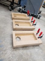
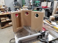
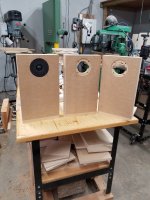
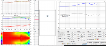
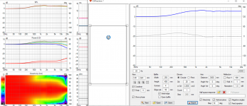
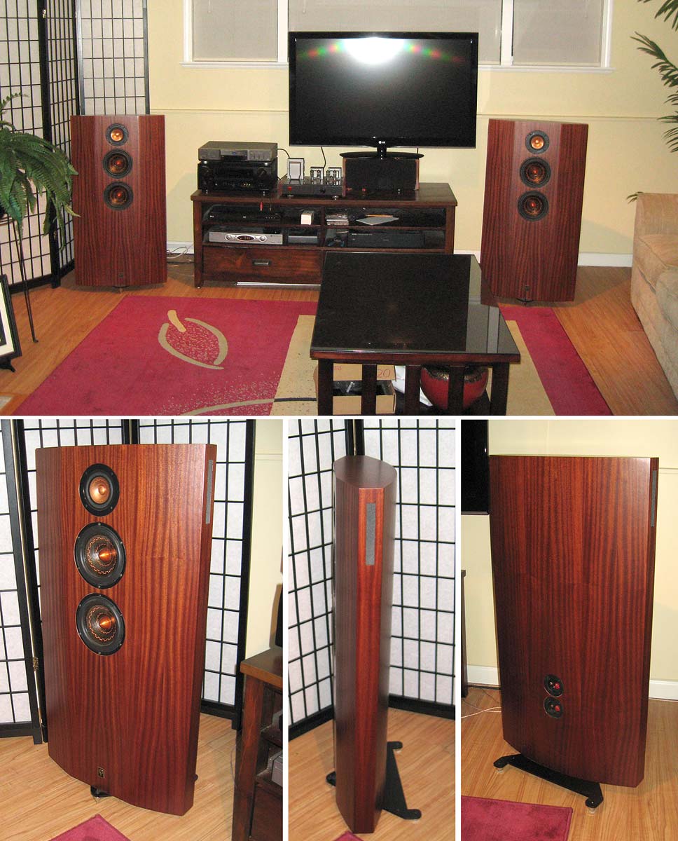
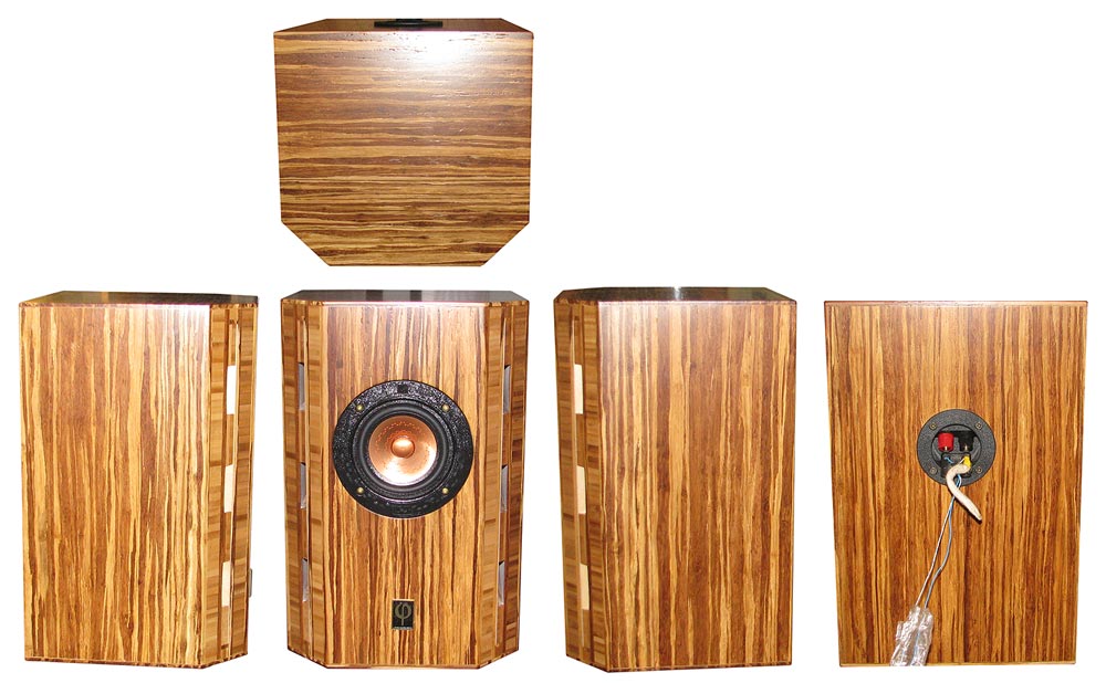
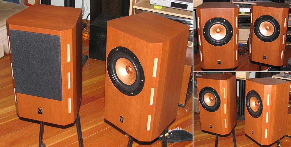
Here are three test baffles that I will be testing incrementally larger edge treatments of roundover, 45° chamfer and double 22.5° bevel with a full range of off axis measurements.
Test tweeter will be a Seas NoFerro 900.
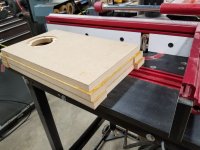
Here are the blanks I will be testing on.
I have always wondered how much difference there was between a roundover and a 45° chamfer. Jeff Bagby once told me to treat a chamfer as a roundover with modeling programs that didn't specifically list chamfer as an edge option.
An edge treatment I have not seen is a double 22.5° bevel, it would seem to be similar to a roundover, but not require a big expensive roundover bit or be hard to veneer.
While various modeling programs allow different sized roundovers and show specific angles, I have been curious to see the incremental difference in edge treatment size as a full range of off axis measurements.
Here are three test baffles that I will be testing incrementally larger edge treatments of roundover, 45° chamfer and double 22.5° bevel with a full range of off axis measurements.
Test tweeter will be a Seas NoFerro 900.
Here are the blanks I will be testing on.
Attachments
Of more importance is getting a big enough radius to be much more than cosmetic; for instance a 2 k/2nd XO requires at least a 1.71 k and preferably a 1 kHz radius = ~34400/2/pi/1000 = ~5.475 cm/2.16", a lot bigger than we normally see on DIY speakers and why I've historically just used a thick enough felt or similar ring around it and foam extensions over the terminus/mouth of horns.
For baffle edges it ideally needs to be baffle step frequency, so basically more round than flat: baffle step diffraction
For baffle edges it ideally needs to be baffle step frequency, so basically more round than flat: baffle step diffraction
I've done this a few times flat router bits. Can't say as I've ever measured or heard a diff between them and roundovers.An edge treatment I have not seen is a double 22.5° bevel, it would seem to be similar to a roundover, but not require a big expensive roundover bit or be hard to veneer.
Roundovers would be easier to veneer in my experience.
Here is some data on chamfers https://heissmann-acoustics.de/en/schraege-fasen/
If I may request please include measurement of naked driver without any baffle what so ever!
As, the wider the baffle the lower frequency it supports and diffracts = bigger roundovers needed to mitigate. Basically roundovers should be as big as possible = start immediately beside the transducer. If lazy with roundovers or don't want do big ones just don't use any baffle or minimal flat baffle around transducer. Got 1/4" router roundover bit? Use baffle that extends only 1/4" around the transducer and get performance similar to wide baffle with huge roundovers, except the baffle support is lost and might make more difficult passive crossover. Best and easiest for diffraction performance though. To fully mitigate diffraction you need to approximate sphere as well as feasible, edge radius >= driver diameter and no flat baffle. Tweeters with huge rim are hard on this, you need big roundovers/slants like GM calculated.
Last edited:
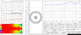
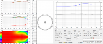
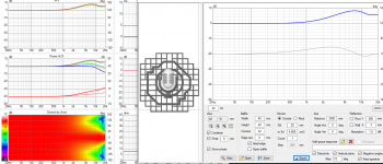
Few quick sims to demonstrate that as one approaches sphere the diffraction related interference gets less. For tweeter it seems any round over is better than no roundover even without any baffle, because the structure around the dome is relatively big. It takes about 5cm roundover to get rid most of the diffraction ripple even without baffle, 5cm roundover around the rim of the tweeter. If tweeter structure was only total 4cm diameter, almost no flat area around the dome, only 1/4" roundover would get rid of diffraction ripple. This small structure is hard to achieve with tweeters, hence waveguides are increasingly popular, easier to get better system performance in many ways including diffraction because it takes the small tweeter appear physically bigger, possibility to get rid of the flat baffle.
Sorry polluting your thread, just an interesting topic and looking forward if real world measurements and chamfers have similar effect to simulated ideal roundovers")
Sorry polluting your thread, just an interesting topic and looking forward if real world measurements and chamfers have similar effect to simulated ideal roundovers
Attachments
-
 naked-tweeter-with-rim.png132 KB · Views: 156
 -
 naked-tweeter-with-rim-roundovers.png126.4 KB · Views: 148
 -
 naked-tweeter-wo-rim.png122.5 KB · Views: 132
 -
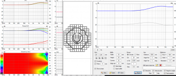 naked-tweeter-wo-rim-roundovers.png122 KB · Views: 131
 -
 naked-tweeter-on-baffle.png132.2 KB · Views: 129
 -
 naked-tweeter-on-baffle-50mm-roundover.png124.7 KB · Views: 143
Last edited:
As, the wider the baffle the lower frequency it supports and diffracts = bigger roundovers needed to mitigate. Basically roundovers should be as big as possible = start immediately beside the transducer.
My simulation experiments have led me to the exact same conclusion.
I am looking forward to this acoustical experiment, DaveFred.
Very interesting. I'll be following this too.
Another variant would be the reverse round-over.
You know, with a super-large radius, eg. 40". It could be concave and axisymmetric like a very shallow horn, or asymmetric... like... a elliptical waveguide?
Surely there must be some software that could simulate this...
Another variant would be the reverse round-over.
You know, with a super-large radius, eg. 40". It could be concave and axisymmetric like a very shallow horn, or asymmetric... like... a elliptical waveguide?
Surely there must be some software that could simulate this...
Last edited:
Is there a conclusion on this? For tweeters the sphere is best, followed by the truncated pyramid...Of more importance is getting a big enough radius to be much more than cosmetic; for instance a 2 k/2nd XO requires at least a 1.71 k and preferably a 1 kHz radius = ~34400/2/pi/1000 = ~5.475 cm/2.16", a lot bigger than we normally see on DIY speakers and why I've historically just used a thick enough felt or similar ring around it and foam extensions over the terminus/mouth of horns.
For baffle edges it ideally needs to be baffle step frequency, so basically more round than flat: baffle step diffraction
My thinking says "it depends" - mostly on frequency. One size and shape doesn't fit all, so it's always a compromise.
https://www.diyaudio.com/community/...ge-treatments-for-tweeter-diffraction.346178/
https://heissmann-acoustics.de/en/schraege-fasen/
https://www.diyaudio.com/community/...ge-treatments-for-tweeter-diffraction.346178/
https://heissmann-acoustics.de/en/schraege-fasen/
Last edited:
Let's stand on the shoulders of giants like Olson and repeat the figure on p23 here (again). His famous research sadly mainly focused on on-axis response, but the sum of diffraction sources and (small) speaker is clearly given here. Always a nice starting point.

Of more importance is getting a big enough radius to be much more than cosmetic
Given a fixed material thickness a chamfer will give a larger “effective” radius.
We did do one box that was first drawn as a 30° followed by a 45° chamfer, but not quite the same thing.
Our full-on miniOnken with the vents down the sides have significant chamfers.
We found that when the chamfer was extended around the box, the speaker’s diffraction signiture further decreases.
Note: none of these use a tweeter as per the OP
dave
Last edited:
Is there a conclusion on this? For tweeters the sphere is best, followed by the truncated pyramid...
No teardropish shape is better than a sphere. Truncated pyramid can resemble a teardrop. And as frequencies drop the chamfer looks more and more like a big roundover.
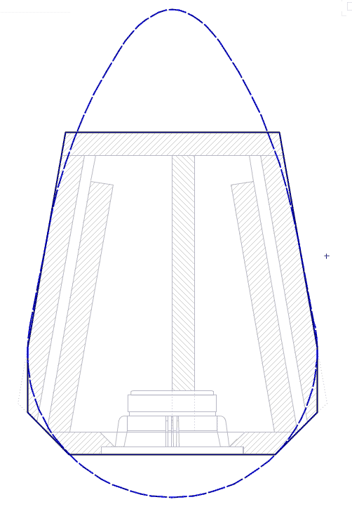
dave
Last edited:
At a glance, certainly seems to be, at least WRT speaker box shapes: Supersonic shapes
I recall that Patrick Bateman has done some experiments that show that baffle step diffraction is influenced by both cabinet depth and the shape of the sides/rear of the cabinet. He speculated that a rounded rear shape would smooth out the diffraction response.
If I can find his post, I will link it.
If I can find his post, I will link it.
Oh, that's all true enough. For high velocities this was well-known to classical shipwrights. Russell expanded on it in a different way, but modern development can in essence be said to begin with the work of Rankine and latterly William Froude from the 1870s (this is actually the subject of a 2-part paper I recently submitted), and it is an integral part of aerodynamics and ballistics as [modestly] high speed branches of hydrodynamics. It's all fluid flow.
Edit: for anyone sad enough to care, interestingly, Newton got there first, albeit his underlying assumptions were partially incorrect. Not entierly though -you have to be careful, since his language was used differently. If you set that aside though, his concepts were actually more complex and in certain respects more accurate than many historians have realised, while the mathematicians have understandably not entirely realised the historical implications for my particular field of interest.
Edit: for anyone sad enough to care, interestingly, Newton got there first, albeit his underlying assumptions were partially incorrect. Not entierly though -you have to be careful, since his language was used differently. If you set that aside though, his concepts were actually more complex and in certain respects more accurate than many historians have realised, while the mathematicians have understandably not entirely realised the historical implications for my particular field of interest.
Last edited:
- Home
- Loudspeakers
- Multi-Way
- Roundover vs. 45º Chamfer vs. Double 22.5º Chamfer edge treatments for tweeter diffraction.