Hi Steve,
Thank you very much for the How-to.
Demian provided the theory and you
provided the details.
Team work.
So I'll connect Lab PS at the bride rectifier, I'll hook probe minus to the
neg bridge and then probe along the traces back to the vReg.
I think I got it. If that doesn't do so well, I can probe minus on the
vReg and probe back to the bridge too.
Cheers,
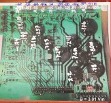
I'm getting there. I have the three bridges with wire extensions.
Did a dry run on it and I'm going to print off three of the pics i made
and write the data on them.
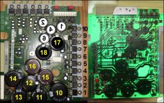
The referenced pic is in post#78, with left board mirror imaged.
Otherwise I'll get lost in all my scribble especially if it on one page.
It kind of tricky because the Bridges feed something farther away then
I would expect. These are the 7 large caps numbers 10 thru 16.
I'll post data when completed, one at a time.
The first pics shows the boards.
In this case the second pic will show A bridge 3.0V through the power supply.
Cheers,
Did a dry run on it and I'm going to print off three of the pics i made
and write the data on them.
The referenced pic is in post#78, with left board mirror imaged.
Otherwise I'll get lost in all my scribble especially if it on one page.
It kind of tricky because the Bridges feed something farther away then
I would expect. These are the 7 large caps numbers 10 thru 16.
I'll post data when completed, one at a time.
The first pics shows the boards.
In this case the second pic will show A bridge 3.0V through the power supply.
Cheers,
Attachments

Last edited:
Here is the Abridge Test.
We have a kid crisis that I have to take care of.
All are voltages, except those with m or mV
depending on space. 2nd is harder to read than I thought.
That same diode is fried. Unsure of cap.
Cheers,
We have a kid crisis that I have to take care of.
All are voltages, except those with m or mV
depending on space. 2nd is harder to read than I thought.
That same diode is fried. Unsure of cap.
Cheers,
Attachments
Last edited:
Well, I can read your voltage annotations but I'm afraid I'm completely lost.
I'll pose some general questions.
From perusal of the manual you sent me, I know there are several line voltage settings available and it seems like the 120 V option is best. Is it selected?
Can you give me a “big picture” summary of the state of the board? For example, are any of the regulator sections working properly re their respective local regulator ground pins?
I know one or more regulators have a known shorted-diode problem. How many regulators fall into this category? I assume we have to defer tackling them until replacement diodes are installed.
Which section(s) have shorted cap issues?
I suggest we choose for repair one section that has only a shorted cap issue for first trouble shoot-exercise, your choice. A supporting circuit sketch would be useful. Does this approach sound reasonable?
Last edited:
Effing unbelievable. All my responses just vanished.
I'm too p-i-s-s-e-d off to type it all back again tonight.
In summary O in the upper middles is the only diode that
always tests as shorted.
Two electrolytics have been replaced, they are in the lower right
where the Bridge A had 3V on it; those caps meaured - 42 mv
the other 19.1 mV.
Bridge A feeds the next to caps, 1.25 v plus 1.76 v equals 3.01v
the full voltage of the 3.0v Bridge. Note there is no amperage reading
from the lab supply, it's dialed up from zero but since this thing is loaded
there is much going on. I guess it's at its equalibrium for lack of the better
term.
I assume those two caps smooth out the voltage to the vRegs on the top row.
inV in blue, and outV in silver. And about 1/2 way through checking vregs
I realized pin one is on the right and pin three is on the left.
This board gets funny in the middle, trying to get measurments the 'voltage
is bouncing around a lot. Maybe oscillation in the few mV level or I'm just
reading the probes and not the devices.
Bridge B and bridge C should be illuminating. I think Bridge B feeds the two caps
that are replaced. '
Regarding the shorted diode...I have other diodes, some have smaller specs
like 1A 200V Some are close like a MUR850. And some stout like 600V 1000V
and 8A.
There is a diode thread in Parts forum where I asked about these diodes.
I can't copy over the data sheets.
I'll get back on it tomorrow.
I'm in that state, where you don't want to touch or do anything.
It might end up against the wall!
Pink Floyd, The Wall: Sadly they got the lyrics wrong.
The lyrics should have been,
"Hey kids. . .leave the prof alone!"
Cheers,
I'm too p-i-s-s-e-d off to type it all back again tonight.
In summary O in the upper middles is the only diode that
always tests as shorted.
Two electrolytics have been replaced, they are in the lower right
where the Bridge A had 3V on it; those caps meaured - 42 mv
the other 19.1 mV.
Bridge A feeds the next to caps, 1.25 v plus 1.76 v equals 3.01v
the full voltage of the 3.0v Bridge. Note there is no amperage reading
from the lab supply, it's dialed up from zero but since this thing is loaded
there is much going on. I guess it's at its equalibrium for lack of the better
term.
I assume those two caps smooth out the voltage to the vRegs on the top row.
inV in blue, and outV in silver. And about 1/2 way through checking vregs
I realized pin one is on the right and pin three is on the left.
This board gets funny in the middle, trying to get measurments the 'voltage
is bouncing around a lot. Maybe oscillation in the few mV level or I'm just
reading the probes and not the devices.
Bridge B and bridge C should be illuminating. I think Bridge B feeds the two caps
that are replaced. '
Regarding the shorted diode...I have other diodes, some have smaller specs
like 1A 200V Some are close like a MUR850. And some stout like 600V 1000V
and 8A.
There is a diode thread in Parts forum where I asked about these diodes.
Id take a minimelf with 1A and reasonable 50nS switching speed. Nothing special.
It is a BYD37J 600v soft recovery diode.
10pf is good with Trr 35nS.Darn you're good Jon, I got only as far as Newark...
Mouser was next on my list.
Cd is good.
It doesn't list Trr which should be < 20ns
These FU1800s have Cd = 10pf and Trr < 35ns
I can't copy over the data sheets.
I'll get back on it tomorrow.
I'm in that state, where you don't want to touch or do anything.
It might end up against the wall!
Pink Floyd, The Wall: Sadly they got the lyrics wrong.
The lyrics should have been,
"Hey kids. . .leave the prof alone!"
Cheers,
Last edited:
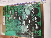
Here is the next image, Bridge B.
Not much different other than voltage
feeding the first two large caps that
the A bridge didn't feed.
Next up is the Bridge C.
Let's see where that takes us.
Checked the voltage setting and fuses 120 VAC
with the 2 correct T3.15L fuses. Cleaned everything
with ISO and reinstalled.
Cheers,
Not much different other than voltage
feeding the first two large caps that
the A bridge didn't feed.
Next up is the Bridge C.
Let's see where that takes us.
Checked the voltage setting and fuses 120 VAC
with the 2 correct T3.15L fuses. Cleaned everything
with ISO and reinstalled.
Cheers,
Attachments
Last edited:
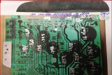
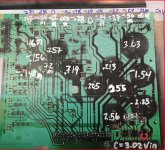
Here are the measurements from Bridge C, 3.02 Vin.
We have voltages on most of the 'lytics.
Voltage on the 5 chip caps by the Bridge C.
Next up are the four Bridge Rectifiers in the upper
left corner. Starting from the heat sink will be
designated D, E, F, G.
Note the lower two large electrolytics, that were replaced
The are series connected and show -2.25Vdc and 2.56 Vdc
these now appear to be functioning normally.
This is now one section that was repaired.
That is all for now.
Cheers,
Attachments
Last edited:
What you're reporting is encouraging.
Let me revise my recommendation about bench supply procedure (my most recent exercise featured a 3.3V supply, hence the 3V voltage suggestion); I suggest the same 100mA current limit for protection; connect the supply across the bulk filter cap and raise supply voltage slowly, watching for current draw, smoke emission, etc. With any luck you’ll be able to raise the voltage enough to see the regulator under test begin working. If the supply goes into current limiting poking around with your DVM should lead you to the defective culprit. You can leave the transformer connected but unpowered; a diode bridge that’s not shorted will block conduction to the transformer. Repeat this debug process at each regulator until all are working. Easier said than done, but one at a time gets it done.
I recall the first time I used current limited DC tracing to locate a board short. (Assuming 100 mA and 0.1mV DVM sensitivity, you can resolve 1 mili-ohm increments in trace resistance). It seemed very much like a mouse is a maze, sniffing for cheese. Each incremental voltage increase meant the cheese was closer. If I ventured down a benign path there was no increase in voltage drop, so I knew to reverse and explore an alternate path in the maze. 😀 Usually I can converge to the problem in only a few minutes without needing to record anything. Of course, a schematic for a road map is very useful.
Steve, that sounds like a plan.
I'll need some time, as Spring Break is here,
my wife and little girl will be home, and I'll be doing family
stuff. When there is an opening....
Cheers,
I'll need some time, as Spring Break is here,
my wife and little girl will be home, and I'll be doing family
stuff. When there is an opening....
Cheers,
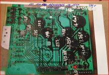
Not much has changed, along the way I've upped the voltage to 10Vdc on the large
bulk cap.
1st run no load
2nd run Xfrmr load
Now in easy to read format.
I'll have to rig it up so that the transformer center connector
are connected to the board for another measurement run.
Thinking I can go higher in voltage, as there is no current going
through the board or very little. 15Vdc, 20Vdc, higher?
Cheers,
Attachments
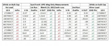
Elevating voltage should be OK as long as you don't exceed cap's or IC's max voltage rating.
18VDC should be enough to make a 7815 regulator deliver.
Curious that with 10V, applied you're not seeing voltage at Vin pin of associated regulator???
18VDC should be enough to make a 7815 regulator deliver.
Curious that with 10V, applied you're not seeing voltage at Vin pin of associated regulator???
That bulk cap goes somewhere, maybe to the motherboard
flat 40 connector at the bottom or side of the power supply board
and connects to some other caps also.
It's the 16V 15,000uF cap that I'm powering to.
Looking at the Bridge B measurement panel, those two caps
13, 14 are 63V 3900 uF. I also got some vRegs voltage input
with them. I guess I'd connect to cap 14 as it and cap 13 are in series.
I'll bump up the voltage to 15 volts on the 16V cap and see what
the vRegs do.
Then I'll solder some prongs on cap 14 and test as 18 volts to start.
Well maybe not, I'll start at 10 volts to see if I get a vReg to fire.
That's the plan anyway.
Cheers,
Typically caps are operated at 1/2 their rated voltage for max reliability. I doubt the Germans would do anything less. So a 15V cap probably supplies a 5V regulator. The 63V caps are for 24V supplies, etc.
I observe that there are 13 "bulk" caps but 16 three terminal regulators, so some of the regulators must share caps. When transformer powered, do all caps show DC voltages measured across their soldered terminals? Are there any that do not and why? Some DVM/continuity probing would resolve some of these quandaries.
Since so many regulators don't seem show regulator output, and because there's such a multitude of connections at the ribbon connector, I speculate that regulator ground sensing is established at the destination modules--- sort of remote sensing, at least for the regulator ground terminals. If this is the case, some regulators may not behave until the ribbon cable is connected to destination cards.
Since so many regulators don't seem show regulator output, and because there's such a multitude of connections at the ribbon connector, I speculate that regulator ground sensing is established at the destination modules--- sort of remote sensing, at least for the regulator ground terminals. If this is the case, some regulators may not behave until the ribbon cable is connected to destination cards.
All of the large caps had voltage on them at least 1/2 their rated voltage when
powered by the line voltage. There was one section where regulator had issue
and that was with the one with the failed diode vReg 6 of 10.
Caps 14 & 13 were replaced with higher lower capacitance and higher voltage
units because they were the closest that I had on hand.
What one person did I can't recall if it was in the earlier UPD Help thread was
replace all the caps on the board and touch up all the 5V solder joints. I'll have to figure
out which joints those are.
These electrolytics are all 25 plus years old. Yes, I know they may all test good but for how long?
I might as well order some replacement diodes. I haven't even looked into the SMPS
and their capacitors either.
I probably should just replace that one diode with some that I have in stock,
a 1n4007uf cap. It may not short out like it's supposed to, but it should "fix"
that local area if that was the only issue?
And one of the original questions that I had was this:
Can I apply a direct voltage to the vReg input and measure it's output
to see if it still works?
Maybe at 1/2 their rating?
The supply voltage does not have a number on the dial to set the current,
it's LEDs and you don't know what it will say until it illuminates.
Same with the voltage.
Steve, you may be correct, the grounds go through to the ending locations
so the vReg operates with "feedback" from that location to provide the
voltage required at the end location.
Which meas it needs to be reassembled and all the cards put back together to find
out if there is an analog power supply problem.
So, does shot gunning all the caps in the analog power supply make sense now that I have
it out? Or am I "Crusin' for a bruisin'" and will end up in never never land?
It did work once. And then one time it didn't fully turn on or whatever R&Ss term
for it it. "The UPD does not run up."Ch4, sec.4.3, p4.1 UPD manual with Chapter 4 after
B Appendix, if so configured.) I did purchase a better battery then the one described
it has twice the mA hours. I should just put it in the little box on the chassis wall and wire tie it back in so it's ready for reinstall along with the mutha' board and cards.
I need to finish cleaning the gray slime out of the mother board socket and one of
the other cards. So far, lacquer thinner removes it with least effort. Still not so good
but it works. If I still had some "Bestine" (removing and thinning rubber cement)
I would use that. One thing to not use
is acetone as it's would eat into the coating on the board and the IDE female
receptacle for receiving the boards.
For the negative supply voltages, I'd just hook up the neg voltage to Vin and
pos voltage to GND.
Any thing I missed?
Yes, I tested the two caps pulled, 14, 13, the questionable 14 cap measured 12M Ohms, the other (13) 13K Ohms.
That means they should be good. Obviously 14 is much higher resistance then 13.
EST and C test. I'll check it with DER EE.
Cheers,
Last edited:
Hi Sync,
If you can confirm the path from regulator Vin to its respective bulk cap "hot" pin, it should be perfectly Ok to install a temporary jumper from the regulator's ground pin back to bulk cap's ground terminal. Gradually bring up applied bench supply, watching for undue current draw. As you raise the bench PS voltage, you should see the regulator voltage rise and then clamp at its nominal rated output voltage. During this test, I'd disconnect the ribbon cable as a precaution; of course restore to normal once regulators are working properly.
My personal religion is to not replace caps unless they show obvious leakage or deficient performance; bulk supply caps like we're discussing are especially to test in circuit--- if they don't show excessive ripple and are comfortably above regulator drop-out, I deem them OK.
Forgot to mention diode substitute--- I think a 1N4002 or higher ought to be fine; these are linear regulators and switching speed shouldn't be much of an issue.
Steve,
I understand.
First find which cap to regulator.
Then jumper to neg terminal on that cap. (simple to solder small lead
to attach jumper too. Once you and Demian mentioned that, I saw the light.
For some reason it never occurred to me that I could do this and sadly
the instructors at community college had not updated their skills and
knowledge since they left school. One instructor didn't know pots
had different tapers. One question was from a given pot of X value and it's turned
1/2 way...solve the problem. When I asked what the taper on a pot was as
that would determine the correct answer. He responded I think linear,
what other taper could there be? I replied, Audio, Log, reverse log,
custom, etc. Needless to say...he got p-i-s-s-e-d off at me for asking.
I digress.
Yes, wilco.
Obvious leakage, like seeping stuff out of the cap or leakage is one of those "things".
Or would that be X% of dc applied voltage?
How big would the squiggleys look on a scope?
Comfortably above regulator drop-out voltage.
If the vReg is a 5 V unit and the cap is a 16V cap?
Or when the vReg clamps while DC source continues
to rise. Do I keep upping the voltage to the rated cap voltage
to confirm? or go to 10V on the 16 Volt cap circuit.
Finally, the testing of bulk caps in circuit showing excessive ripple...again
sorry I don't have enough experience to know what is excessive ripple.
Cheers,
Back later, have to take my little girl out and dogs for exercise.
As agent Smart would say, "Oh yes, it's the old reply to the thread while
I'm responding trick, again."

And do as I say, not as I do. Imagine that.
I understand.
First find which cap to regulator.
Then jumper to neg terminal on that cap. (simple to solder small lead
to attach jumper too. Once you and Demian mentioned that, I saw the light.
For some reason it never occurred to me that I could do this and sadly
the instructors at community college had not updated their skills and
knowledge since they left school. One instructor didn't know pots
had different tapers. One question was from a given pot of X value and it's turned
1/2 way...solve the problem. When I asked what the taper on a pot was as
that would determine the correct answer. He responded I think linear,
what other taper could there be? I replied, Audio, Log, reverse log,
custom, etc. Needless to say...he got p-i-s-s-e-d off at me for asking.
I digress.
Yes, wilco.
Obvious leakage, like seeping stuff out of the cap or leakage is one of those "things".
Or would that be X% of dc applied voltage?
How big would the squiggleys look on a scope?
Comfortably above regulator drop-out voltage.
If the vReg is a 5 V unit and the cap is a 16V cap?
Or when the vReg clamps while DC source continues
to rise. Do I keep upping the voltage to the rated cap voltage
to confirm? or go to 10V on the 16 Volt cap circuit.
Finally, the testing of bulk caps in circuit showing excessive ripple...again
sorry I don't have enough experience to know what is excessive ripple.
Cheers,
Back later, have to take my little girl out and dogs for exercise.
As agent Smart would say, "Oh yes, it's the old reply to the thread while
I'm responding trick, again."
And do as I say, not as I do. Imagine that.
Last edited:
Reading up and studying the data sheets.
It will take me a bit of time.
Then, I'll madly apply voltages to the capacitors until they cry "UNCLE."
Found a recurring error in the10X line up. The cap after LT1086
is the LM2940, not LM7940!
And as Steve mentioned there are plenty of 1N4002 diodes providing
protection, even in the data sheets.
I just wish the data sheets had the various resistor values for setting the output voltage. Yes, it's shown following. And not needed but from out to in
the 1n4002 diode goes over the top cathode band to in.
Standard values are out there somewhere.
I'll google in a minute.
I did and with the LT1086 it develops a 1.25V reference voltage
between the output and the adjust terminal. I can check on the math.
If I recall there is a 10mA required basic current to keep the vReg
stable. Then there is the Iadj at 50uA
121Ohm
---------- = 5V
365 Ohm
124Ohm
---------- = 12V
1070 Ohm
Now I can have a look and see what the LT1086s are set up to deliver.
Cheers,
Attachments

Last edited:
- Home
- Design & Build
- Equipment & Tools
- Rohde & Schwarz UPD: Troubleshoot then Restore to Glory