Sync
I get a spinning LOADING message when I try to get your data--- not sure where where the bug lies. You might try posting again.
Thanks
Steve
Fixed. Mega length urls (million + characters) are the cause. I have deleted an image link in the posts above.
Thanks again, Mooly.
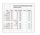
UPD Focus:
This is strange to me.
This chart shows which vReg In pin
has continuity with one of the bulk caps.
Not all do and some are kind of funny.
They connect to most of the bulk caps
then nothing. I'm guessing some of the caps
charge? Or the smaller SMD caps charge up
and stop the continuity test voltage.
Yes, every bulk capacitor had voltage across
their pins when powered up through the transformers.
The data is below and I remembered not to post
the pics in this window.
Cheers - almost,
Attachments
Your reported data likely presents a confusing and frustrating picture.
One thought is to assume any damage from power supply problems has already occurred so that powered trouble-shooting is worth the added risk.
IF you're feeling bold re the exposure to further damage, you'd simply reconnect modules, apply power, and probe all 3-terminal regulators to sort problematic regulators versus those that work.
I don't intend to advocate such a course--- it might be expeditious or it might lead to added heartache. Maybe you've already had the UPD back into a powered state. But if you prefer to be cautious, I'll try to formulate next measurement suggestions. Your thoughts?
I presume that you have located the ground points for every analogue and digital circuit - and measured R between voltage rail and GND? This is an old machine and there is every chance that a decoupling cap (or other item) has lower R than it ought to. Very important! Forgive me if I already suggested this!
thermionic, No, I haven't located the ground points for every analogue and digital circuit.
and have not measured R between voltage rail and GND. I cannot do it with any accuracy
at the moment as I don't know where the rails are, I don't have a schematic either.
While there might be clues...I'm doing what I can at the moment.
I'm getting closer though and starting to envision the analog power supply as
many different power supplies configured in a multitude of different ways,
using two transformers, parts are series connected with eight bridge rectifiers
supplying 16 local voltage regulators. And they are a cluster f o f capacitors
all series-ed paralleled with all kinds of SMD caps, resistors and diodes in and
around the vRegs.
While I get pulled with two other projects taking shape,
the UPD has been simmering in my head. I can try and
anticipate at least where the rails might be and see where that leads
but for the moment it's disassembled and in the queue.
Steve, no powered state yet with the UPD together. I'm open to suggestions for
measurements, please. It may just be some more iterations until I see the light.
It's off in the distance, but it has increased a few lumens.
Now, I'm not sure how I'd measure low r from cap to the rail or cap to the ground.
I drew out some of the common configurations of the vRegs and what the data
sheets describe as how to beef them up for lack of a better term.
With diode from output to input, along with additional capacitance wired in
from ground/adj to output, some have resistors also.
That is about what I'm thinking for now.
I'll see if i can find one of these and draw it out a bot more.
Maybe it's also drawing out the bulk caps even if i don't know
which or what they are filtering and how all the other caps fit in.
It's unsettling to see the nine bulk caps all connected together
in seeming mish mash of connections. But slowly the circuit
is starting to unveil itself the more I go through it.
And, that's about all I can describe at the moment.
I'll get there, it's just a matter of when.
I still have to get the grey sticky slime out from under the motherboard's IDE interface.
Cheers, while I'm scratching my cranium.
Last edited:
On one of our UPVs, there is a short between -15v and 0V on the analogue board. This has taken out the PSU rail, and I haven't had a chance to work out yet if it's just the VReg that's got the issue (most monolithic VRegs have short protection), or - more worryingly - if it's damaged a Trafo secondary...
I will either have to borrow a thermal camera or spray suspect items with freezer spray, whilst gently powering the board from a lab PSU, in order to locate the failed component.
The greater worry is whether the transformer is damaged...
So, the point I am making to you is: don't get caught in the same trap. If you rebuild the PSU and it's tickety-boo, you don't want to induce a failure due to a shorted cap somewhere. There is no guarantee that a fuse will go, or Vreg short protection will trigger - there is always a risk of damage.
You can easily work out where +V and -V points are by looking up opamp pin-outs. You may find that some hover on 'virtual rails', decoupled from other circuits, so look for commonality and patterns before making a judgement.
That is going to be fun, trying to figure out where the OpAmp supplies go from the
circuit card to, (what do we call the female connector part the IDE card slot on the mother board? ) motherboard, to connector back to the analog power supply. I think that might be getting ahead of myself, for now.
However, both you thermionic and Steve are helping me begin to make sense of this,
little by little. Somewhere lurking in the background is jeanlucdemarc, and Demian.
I also need to go back and review Marc's data as he thinks mine might be the same
as his and there might not be an issue.
Let me cogitate on this for a little while and see what I can come up wtih.
First, I'll measure rail to ground.
QUESTION: Wouldn't measuring R from vReg out have the same potential as the voltage rail?
The grounds on this analog supply board are tricky.
The "Oracle of Sync" told me I would have more board analysis work in the near future.
Imagine that! I should listen to her more often now that I know she's correct.
Cheers,
Post Script, no pics for the time being - there is nothing new of which to take a pic.
Last edited:
In an earlier post you asked about powering regulators with bench supply from between reg's ground to Vin terminal. I think this has relatively low risk if you use a current limited supply ( about 20 mA) and have ribbon cable disconnected. Raise supply voltage slowly and watch for the unexpected. You should see Reg output rise with increasing applied voltage until it reaches its expected output.
In the case of the "adjustable" regulators, use the normally grounded end of the feedback resistor divider as the connection to the bench supply. Eg.the ground end of R2 of the thumbnail in post 100.
In the case of the "adjustable" regulators, use the normally grounded end of the feedback resistor divider as the connection to the bench supply. Eg.the ground end of R2 of the thumbnail in post 100.
Last edited:
That might be the plan Steve.
I'll take a shot at it and see where it leads.
This is in line with lab supply to vRegs vIn and jump the vRegs ground to the
bulk cap ground terminal watch and check the output.
Configure for pos or neg vReg output.
I'll provide results in a bit.
Cheers,
I'll take a shot at it and see where it leads.
This is in line with lab supply to vRegs vIn and jump the vRegs ground to the
bulk cap ground terminal watch and check the output.
Configure for pos or neg vReg output.
I'll provide results in a bit.
Cheers,
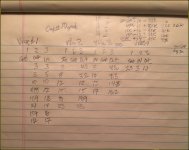
I have some measurements.
vRegs 1, 2, 3 track the input voltage nicely.
vReg1: 3Vin 3Vout thru 17Vin 17Vout
vReg2: 5Vin 4.5Vout thru 25Vin 25Vout
v Reg3: 5Vin 4.3Vout thru 17Vin 16.2Vout
Unsure about the connections on the Neg vReg.
vReg4 the Neg reg,
p1- gnd Supply Pos Volt red [Meter 2.5V]
p2- in Supply Neg Volt black [Supply 3V] Meter Neg (black)
p3-out Meter, Pos Red. [Meter 1.1V]
I should switch meter leads then I'd get the negative voltage from them.
It didn't seem correct for some reason.
Cheers,
Last edited:
There was something in the datasheet about the vReg would have proper regulation when the input Voltage is 2V higher then the output Voltage.
Now I'll have to go find it.
I didn't want to test to the bleeding end, (i.e.; testing vReg1 to see if greater than 20V input the device shuts down.)
Testing 17 Vin on a 15 Volt Reg, and it's putting out 17Volts for me I don't have any complaints about it.
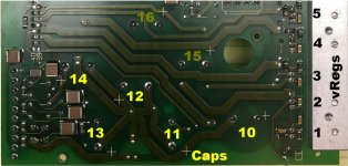
The ground for connection on these was connected to Cap #10s Negative Terminal.
The bulk capacitors 10, 11, 12, 13, 14 share the following terminals:
10 - with soldered 2mm piece of 18 awg tinned solid wire.
11 +
12 -
13 +
14 -
I also replace the faulty diode. It's not pretty but its functional.
It's off the board about 1/2 mm. I didn't want to fool around and
try to have the big diode lay flat...it was held in place with forceps
until the solder flowed.
Yes, I'm being overly cautious, if parts start popping on me and
with sacred smoke being released, this is still a nice piece of gear
and I don't want to be the one to destroy it. I'm not doing the
boundary/failure testing. It's hard enough working on this
with out a schematic.
Pics haven't come out of the lab yet.
Cheers,
Now I'll have to go find it.
I didn't want to test to the bleeding end, (i.e.; testing vReg1 to see if greater than 20V input the device shuts down.)
Testing 17 Vin on a 15 Volt Reg, and it's putting out 17Volts for me I don't have any complaints about it.
The ground for connection on these was connected to Cap #10s Negative Terminal.
The bulk capacitors 10, 11, 12, 13, 14 share the following terminals:
10 - with soldered 2mm piece of 18 awg tinned solid wire.
11 +
12 -
13 +
14 -
I also replace the faulty diode. It's not pretty but its functional.
It's off the board about 1/2 mm. I didn't want to fool around and
try to have the big diode lay flat...it was held in place with forceps
until the solder flowed.
Yes, I'm being overly cautious, if parts start popping on me and
with sacred smoke being released, this is still a nice piece of gear
and I don't want to be the one to destroy it. I'm not doing the
boundary/failure testing. It's hard enough working on this
with out a schematic.
Pics haven't come out of the lab yet.
Cheers,
Attachments
Last edited:
From editing prior post but I couldn't finish there as ADMINISTRATION will only allow 30 minutes from posting to to fix or add information, or un-fornaticate it so Everyman can understand it.
That said, here is the information from the two prior postws that I couldn't put in:
I should switch meter leads then I'd get the negative voltage from them.
It didn't seem correct for some reason.
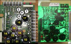
Steve, I chose not to try to solder a 2mm wire on the ground end of the resistor R2.
If you look at pic following, next to the vReg 1, that would be the SMD resistor paralled
to the SMD Cap sticking out toward the cap number 10. I think it would do more harm
then good. So for these tests I just hooked it up to cap 10s negative terminal. In the
lower right corner of the pic.
Cheers,
That said, here is the information from the two prior postws that I couldn't put in:
I should switch meter leads then I'd get the negative voltage from them.
It didn't seem correct for some reason.
Steve, I chose not to try to solder a 2mm wire on the ground end of the resistor R2.
If you look at pic following, next to the vReg 1, that would be the SMD resistor paralled
to the SMD Cap sticking out toward the cap number 10. I think it would do more harm
then good. So for these tests I just hooked it up to cap 10s negative terminal. In the
lower right corner of the pic.
Cheers,
Attachments
Last edited:
I'm sympathetic to conservative thinking! 😉Testing 17 Vin on a 15 Volt Reg, and it's putting out 17Volts for me I don't have any complaints about it.
The ground for connection on these was connected to Cap #10s Negative Terminal.
The bulk capacitors 10, 11, 12, 13, 14 share the following terminals:
10 - with soldered 2mm piece of 18 awg tinned solid wire.
11 +
12 -
13 +
14 -
I also replace the faulty diode. It's not pretty but its functional.
It's off the board about 1/2 mm. I didn't want to fool around and
try to have the big diode lay flat...it was held in place with forceps
until the solder flowed.
Yes, I'm being overly cautious, if parts start popping on me and
with sacred smoke being released, this is still a nice piece of gear
and I don't want to be the one to destroy it.
Cheers,
If you apply 17 at Vin and see 17V out, I'll wager you also will see 17V on the reg ground terminal. Nothing is connected, so the three terminal regulator is a just a blob tied to +17 until you attach its ground terminal to minus terminal on the bulk cap (Cap 10). When working you should see 15V not 17V. You want to make sure the reg is not shorted out to in--- that would be BAD for downstream circuitry.
Last edited:
Steve, I chose not to try to solder a 2mm wire on the ground end of the resistor R2.
If you look at pic following, next to the vReg 1, that would be the SMD resistor paralled
to the SMD Cap sticking out toward the cap number 10. I think it would do more harm
then good. So for these tests I just hooked it up to cap 10s negative terminal. In the
You're wise to avoid tacking wires to SMT unless carefully stress-releaved--- my own bitter experience remembered. But if you trace PCB tracks, I imagine they will lead to the ribbon connector header where it would be safe to attach test wires. Devising a way to verify a working regulator would be good.
Steve, It may be shorted? But then all these VRegs outputs
tracked Vin. Again there is no loading, transformer or motherboard
connections.
electronic, thank you much for those and I'm sure they will help me out.
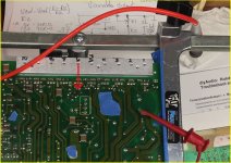
The W20 flat cable is soldered to the analog power supply board.
This is shown partially in the pic in post #111, the upper left
corner. Let me find the full pic and post it here so we don't
have to run around and look for it.
I've selected the mirrored version, the left side is the mirror
of the trace side on the right half of the pic.
As shown, the W20 connector is left center in both halves.
We can see both sides of the board.
Recall I've now replaced three components, that 2nd diode at vReg 6,
the diode farthest away from vReg 6 pins.
Then Cap 13 and Cap 14 were replaced. I don't think it will be an issue
reinstalling the original Cap 13 and Cap 14. I can do some additional
measurements when reinstalled and see if anything changes.
Cheers,
tracked Vin. Again there is no loading, transformer or motherboard
connections.
electronic, thank you much for those and I'm sure they will help me out.
The W20 flat cable is soldered to the analog power supply board.
This is shown partially in the pic in post #111, the upper left
corner. Let me find the full pic and post it here so we don't
have to run around and look for it.
I've selected the mirrored version, the left side is the mirror
of the trace side on the right half of the pic.
As shown, the W20 connector is left center in both halves.
We can see both sides of the board.
Recall I've now replaced three components, that 2nd diode at vReg 6,
the diode farthest away from vReg 6 pins.
Then Cap 13 and Cap 14 were replaced. I don't think it will be an issue
reinstalling the original Cap 13 and Cap 14. I can do some additional
measurements when reinstalled and see if anything changes.
Cheers,
Attachments
Sorry for implication that the reg is shorted, though that's possible. More likely, it's presenting the same voltage at all three terminals because there's no connection to either its output or ground pins; your DVM is a vey high impedance load (11M ohms?), so even moderately high internal resistance between the regulator's pins will deliver nearly the same voltage as Vin.
Coaxing the regulator into operation confirms there's no short as well as assuring nominal supply to destination boards--- a clear advantage for any troubleshooting to follow.
PS So the ribbon cable is soldered rather than a plug and socket pair?
Coaxing the regulator into operation confirms there's no short as well as assuring nominal supply to destination boards--- a clear advantage for any troubleshooting to follow.
PS So the ribbon cable is soldered rather than a plug and socket pair?
Last edited:
Both, soldered on the analog power supply board,
then connected to another ribbon cable from the UPD Chassis.
No worries Steve. This is a process thing. Pointing fingers
and saying EFF-words doesn't move anyone forward.
AND
As we've learned processes are iterative, so from time to time
we revisit what we know, don't know, think we know and
fill in with new scientific data (hopefully). Spelled with a
capital H.
I'll drink to that, 'course I'll drink to anything with a cause.
I won't comment about inhalation events.
At least for 10vRegs, 1 - 3.
vReg 4, the first negative
powered vReg, I reversed the leads from lab power supply, that is
vIn neg and pos to the Cap10 negative.
The meter pos shared the vIn neg,
while the meter neg was clipped to vReg GND pin.
A lot of words for 4 connections.
Pic of raw data on way.
Cheers,
Post Script: Add Pic - reminded me of my accounting days Additional Paid In Capital.
Care to share your bitter story about measuring vRegs? It might help
keep me or Everyman who is following along from the same fun.
Attachments
Last edited:
Any damage done? Use a current limited supply if available!
Edit: Maybe I'm misconstruing--- no damage?
I note in your tabulated data there's no measurement of the ground terminals of the 3-terminal regulators. Measure them--- I'm guessing you'll find the GND pin is floating near Vin voltage. You've got to connect this pin to circuit common for the reg to function.
Last edited:
- Home
- Design & Build
- Equipment & Tools
- Rohde & Schwarz UPD: Troubleshoot then Restore to Glory