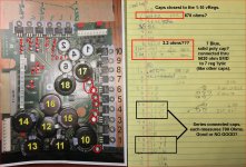
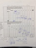
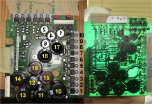
I wrote the pin numbers in the chart so that I could check the VinSpike-
I marked the suspicious voltages on this version of your chart. Those all need to be reviewed because they do not make sense.
1) Are you checking the regulator voltages against their local ground or some common ground? I think there are 3 to 6 floating supplies that only interconnect on the analog boards. That could explain the 0v in measurements.
and Vout referenced to the ground pin.
Yes, I'll get them later.2) On the LT1086 can you check the associated resistor values that are programming them?
Yes, I'll get them.3) Measure the DC resistance across the output caps following their polarity. Any that are below 1K may point to a failed component.
In the 10X vRegs they both LM2940s are marked -5.0 P+4) Can you read the - number on the LM2940's? That would be the voltage set internally.
I will check their data sheets.5) I always find it helpful to download the datasheets on the parts giving me trouble. it makes everything easier when you can see how they are used. I think only a few of the regulators are adjustable.
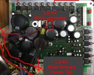
Steve, the significance is those are the transformerDittos to Demian's post above!
I'm not convinced that left hand table in post 55 has any real meaning. The readings may a function of inter-winding capacitance and have little significance.
secondary voltages.
I will. And I understand what you areWhat is the Black/Yellow wire you reference connected to? To help clarify the transformer configuration, would you test the designated cells for continuity in the matrix below? (I tried to save in Xcel file but Xcel won't cooperate 🙁
getting at also. If some of the secondaries have a center tap it would be nice
to know what it is. The Black/Yellow wire is common ground to the larger
heat sink.
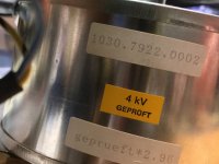
RE the LT1086CT vRegs, they have the date code on them which reads
0506 on all.
I have a bit of time let me get on this before the house gets busy again.
Cheers,
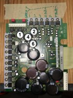
Here is the pic of the 10x and 6x vRegs.
NOTE: You can zip the excel file.
I was going to do that and post my excel "work book".
I've got the different measurement types each in their own workbook. Its the 1, 2, 3 folders
at the bottom and they can be renamed, moved around etc. Each doesn't interact with the
other workbooks, (unless you code that, I'm sure you can if you want, but I've not done that).
And the newer excel has feature-itis, it wants to do EXCEL not what the human wants,
so now you've got to Eff with everything.
Enlarged so it wouldn't be missed.

This round is on me gentlemen.
Let me measure and I'll be back soon.
Cheers,
Attachments

Last edited:
I figured out that diyaudio prohibits Xcel file uploads but I can PM the file if you wish.
In the spreadsheet, I pasted the matrix arrays twice. My thinking is the first matrix will depict paths that show continuity. The duplicate matrix could then show the AC Volts produced at proven winding pin pairs.
I'll make one in my excel, I get it. I have to print some of this and
do some general admin stuff to keep track of what I'm doing here.
Cheers,
Putting the raw data here.
Steve, how to measure the continuity?
With the connectors connected to the power supply and measure
continuity across the pins in matrix on the board?
With the connectors disconnected (floating) and measuring
pin to pin?
Prepping for the transformer continuity, I realized, the following:
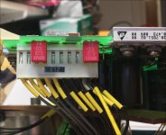
The primary side of theX13 (4KV transformer) connector transformer connects to
the EMI, or next to it.
The primary side of the X12 connector transformer connects
only to the Power Supply Board through to small red blue
wires and has a black yellow ground connection to the
big heat sink. No, I haven't measured the red/blue primary
we'll see.
Cheers,
Steve, how to measure the continuity?
With the connectors connected to the power supply and measure
continuity across the pins in matrix on the board?
With the connectors disconnected (floating) and measuring
pin to pin?
Prepping for the transformer continuity, I realized, the following:
The primary side of theX13 (4KV transformer) connector transformer connects to
the EMI, or next to it.
The primary side of the X12 connector transformer connects
only to the Power Supply Board through to small red blue
wires and has a black yellow ground connection to the
big heat sink. No, I haven't measured the red/blue primary
we'll see.
Cheers,
Ideally, you want to measure only the transformer with no other paths available to prevent any uncertainty. The goal is to find all transformer leads and how they are connected.
I know nothing about this instrument, so some of the details you describe leave me lost. But it sounds like you're hot on the trail.
I know nothing about this instrument, so some of the details you describe leave me lost. But it sounds like you're hot on the trail.
Steve,
Got it. I'll pull off the connectors, that is simple to measure.
That will be in the next batch of measurements.
Please PM me your email address so I can send you the manual.
If you find yourself tired and cannot sleep,
it works better then counting sheep,
count the pages of the UPD.
Demian,
Here are the cap measurements, for all the electrolytics on this
power supply board. It was tricky to find which lead was the cap
etc but I got it done and the results show some problem areas.
This is raw data scribblings, but readable I hope.
I've included pics of your concerns Steve, because you asked,
hope this clears up some questions you had.
Cheers,
Attachments
-
 05.03 -3 2.5 KV Primary & CentTap.jpg255.3 KB · Views: 103
 -
 05.03 -2 2.5 KV Xfrmr.jpg62.6 KB · Views: 110
 -
 05.03 -1 2.5 KV X12 CONNECTOR.jpg82.6 KB · Views: 110
 -
 05.02 -3 4KV Xfrmr Primaries.jpg90.2 KB · Views: 108
 -
 05.02 -2 4KV Xfrmr.jpg70.2 KB · Views: 111
 -
 05.02 -1 4KV X13 CONNECTOR.jpg52.1 KB · Views: 111
 -
 05.01 -3 BlueCap & STD Lytic.jpg63.9 KB · Views: 148
 -
 05.01 -2 CapResistance.jpg510.2 KB · Views: 147
 -
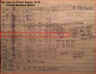 05.01 -1 CapResistance.jpg348.3 KB · Views: 145
Last edited:
Now that I've identified suspect caps,
Pull them and measure again?
1. UCC SMH 63V 3900uF
2 X10 Cap, HFG 25V 100uF 105*C
1 unk 50V 22uf solid cap
1 std lytic cap
Then I have some close replacements
I'll wait for the moment.
Pull them and measure again?
1. UCC SMH 63V 3900uF
2 X10 Cap, HFG 25V 100uF 105*C
1 unk 50V 22uf solid cap
1 std lytic cap
Then I have some close replacements
I'll wait for the moment.
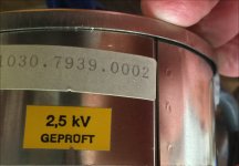
1) the KV ratings are the voltage breakdown test voltages.
2) that "ground wire may be a shield. Its very unlikely they would run the centertap away from the main leads, that a way to add hum to everything inside the loop.
3) the 2.2Ohm measurement suggests a short. Check the lead resistance (short the tips together) for a baseline. look at the PCB for anything that could be causing a shot across the caps. Remove the easiest one first. The big SMD caps will be a pain the remove and unlikely to break- but it does happen.
4) remove the easiest cap and measure the DCR, continue until the resistance comes up. It could also be a shorted diode in the bridge, which can cause all kinds of havoc.
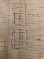
Here is the latest in Transformer continuity.
The X12 first (bottom) I started with Just the X, then went
back and checked resistances between continuity points.
The X13 second (top) The resistances are either side.
At the bottom are three other connectors and their resistances.
X15 is the primary for the smaller 2.5KV.
X10 is a 3 of 4 connector, goes middle of the board.
W1/W10 3 of 4 connector, to the hard drive.
Nothing really stands out to me.
Did a second check of the bigger caps, they are the same w/o transformer.
Cheers,
Attachments
1) the KV ratings are the voltage breakdown test voltages.
2) that "ground wire may be a shield. Its very unlikely they would run the centertap away from the main leads, that a way to add hum to everything inside the loop.
3) the 2.2Ohm measurement suggests a short. Check the lead resistance (short the tips together) for a baseline. look at the PCB for anything that could be causing a shot across the caps. Remove the easiest one first. The big SMD caps will be a pain the remove and unlikely to break- but it does happen.
4) remove the easiest cap and measure the DCR, continue until the resistance comes up. It could also be a shorted diode in the bridge, which can cause all kinds of havoc.
3) Yes I did that before I started, and nulled my leads.
I've only tested the electrolytics. The SMD caps....I'm afraid I'll never get them back on the board 🙁.
For the SMD stuff they need to be pre heated...
and some of the smaller electrolytics, some of the soldering joints
look kind of like crumpled up tin foil, "foily looking"
I did manage to get hold of a hot air repair station with the various tips,
small square, big square, long and short dips etc...I don't want to practice
on the UPD though.
That's about all I can do today.
These measurements were taken with the HP 34401A.
The DER EE 5000 while nice, it's not the workhorse of the
34401A. 21 plus years old and still going gangbusters.
I hear Ricks Coins on the tube in the other room,
nothing quite like those guys pitching over priced
"rare" coins. Just want I want to do, is spend and
extra $1000 on a one ounce gold bullion coin.
I swear, they cull ebay regularly so anything that's near
market price they buy it right up, then double or triple
and bundle so the unsuspecting Joetta buys her hubby
a gift!
Cheers,
Last edited:
"foily looking" = Wave solder. Large areas tend to look that way.
You should be able to check the caps in circuit with the DER. Not precise but will show a dead cap pretty quickly.
You should be able to check the caps in circuit with the DER. Not precise but will show a dead cap pretty quickly.
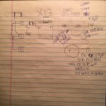
I’ve attached another sketch showing probable transformer secondary windings with connector pin numbers. Would you confirm my interpretation? And if correct, would you measure AC volts across each secondary?
Given the probable center-tap leads, I surmise my earlier sketch depicting two bridge rectifier modules driven by individual windings is likely wrong. Armed with measured secondary voltages, would you trace out a corrected schematic?
Idle curiosity: are all the secondaries in a single transformer?
Thanks.
PS Last night I sent a PM with email address--- did it show up?
Attachments
Last edited:
That would fit my expectation of mixed analog and digital supplies. Also one transformer for source and one for input most likely. I also expect there will be optocouplers between the modules and the host PC interface.
I’ve attached another sketch showing probable transformer secondary windings with connector pin numbers. Would you confirm my interpretation? And if correct, would you measure AC volts across each secondary?
Given the probable center-tap leads, I surmise my earlier sketch depicting two bridge rectifier modules driven by individual windings is likely wrong. Armed with measured secondary voltages, would you trace out a corrected schematic?
Idle curiosity: are all the secondaries in a single transformer?
Thanks.
PS Last night I sent a PM with email address--- did it show up?
Steve, it's a no show. Playing hooky I suppose.
Let me print that off and take some measurements.
I think the transformers are configured more how Demian described after your post.
That is both transformers have secondaries and the larger transformer feeds the second transformer
in part. This is just the analog power supply, there is a SMPS in the center of the UPD as well.
It's probably going to take me a bit to draw in the schematic for the windings.
I'll start with one and then post. Then we can discuss it merits of lack thereof.
The main thing is doing it.
I can then simulate it in mulitsim.
I have LTSpice, but it takes me 10X longer to do anything in it
and I have to figure out how to program what I need.
That is difficult for me. Yes, I know it's popular
and sharable with many more engineers and hobbyists.
Cheers,
Last edited:
That would fit my expectation of mixed analog and digital supplies. Also one transformer for source and one for input most likely. I also expect there will be optocouplers between the modules and the host PC interface.
Hi demian, I didn't see any optocouplers, but that doesn't mean they aren't in
there somewhere, just not obvious to me. So if I were to look
they would be on the various boards where the'll be needed.
Cheers,
Steve, it's a no show. Playing hooky I suppose.
It's probably going to take me a bit to draw in the schematic for the windings.
I'll start with one and then post. Then we can discuss it merits of lack thereof.
The main thing is doing it.
I can then simulate it in mulitsim.
I have LTSpice, but it takes me 10X longer to do anything in it
and I have to figure out how to program what I need.
That is difficult for me. Yes, I know it's popular
and sharable with many more engineers and hobbyists.
Cheers,
The corrected schematic can be hand drawn if you like. The motivation/incentive is to aid accuracy so that we can make sense of observed measurements.
Steve,
Here are the transformer measurements.
X13 was simple.
X12, First was X15 connector to power supply (red, blue) + ground = Nothing.
The added the X10 connector to power supply 3 pin wires 19, 20,21 and the Red/Blue connection.
Revised but have to pic up little girl at school
Here are the transformer measurements.
X13 was simple.
X12, First was X15 connector to power supply (red, blue) + ground = Nothing.
The added the X10 connector to power supply 3 pin wires 19, 20,21 and the Red/Blue connection.
Revised but have to pic up little girl at school
Attachments

While going though that I measured the x10 connector.
Here is the revised sheet.
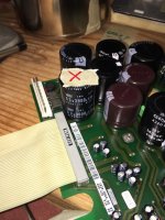
Then I pulled cap #14, and thought I might as well pull #13 it's dulplicate
as well.
I have a stock of power supply caps for various projects however,
they are in a safe place and I'll find them when I need them.
The closest parts were these see pic. They should just fit in the unit. But I'll
look for dedicated caps down the road a piece.
The dead caps is the UCC SMH 63V 3900 uF 85*C replaced with
NCC KMH 80V 2700uF 105*C for now, for testing etc.
The original DCR was OL, but then came around after fiddling with it
to .200Mohms. It measured out at 9.7pF,
when removed DCR OL then .373kohms
ESR 0.1ohm with Cs of 3.23 mF (that's miliFarads 10 -e3 [I think]) not microFarads. The DER EE displays the proper uF when measured.
I need to run down those other three small electrolytics.
Things are messy right now, it is what it is.
Cheers,
Here is the revised sheet.
Then I pulled cap #14, and thought I might as well pull #13 it's dulplicate
as well.
I have a stock of power supply caps for various projects however,
they are in a safe place and I'll find them when I need them.
The closest parts were these see pic. They should just fit in the unit. But I'll
look for dedicated caps down the road a piece.
The dead caps is the UCC SMH 63V 3900 uF 85*C replaced with
NCC KMH 80V 2700uF 105*C for now, for testing etc.
The original DCR was OL, but then came around after fiddling with it
to .200Mohms. It measured out at 9.7pF,
when removed DCR OL then .373kohms
ESR 0.1ohm with Cs of 3.23 mF (that's miliFarads 10 -e3 [I think]) not microFarads. The DER EE displays the proper uF when measured.
I need to run down those other three small electrolytics.
Things are messy right now, it is what it is.
Cheers,
Attachments

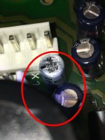
I did start down the path of documenting the power supply starting with
X13, pin 1, 2, 3. but of course the first electrolytic cap on the board was
the failed #14. I couldn't get past that with continuity.
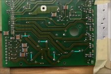
If you look at the underside of the board right there all those big electrolytics
come together right there. I'm guess these cap took the brunt of it and eventually
failed.
Here is the location pic from a prior post.
The location where I started shows, five caps tied together.
Cheers,
X13, pin 1, 2, 3. but of course the first electrolytic cap on the board was
the failed #14. I couldn't get past that with continuity.
If you look at the underside of the board right there all those big electrolytics
come together right there. I'm guess these cap took the brunt of it and eventually
failed.
Here is the location pic from a prior post.
The location where I started shows, five caps tied together.
Cheers,
Attachments
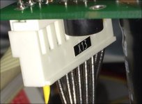
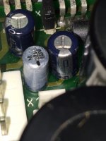
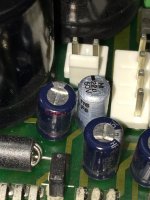
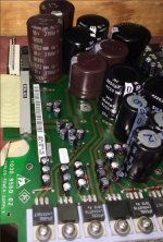
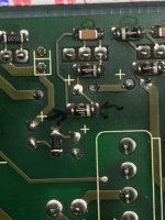
The latest from designated mini capacitor #6 that measured 2.2 ohms.
I'm pretty sure the problem isn't the cap, it's the diode, presumably a zener.
These measurements were using my little Fluke 112 hand held multimeter.
It's small and portable and was recommended to me along with the 114
by my local calibration lab.
All the other diodes that side of the board, using standard polarity, test at .5xxVdc.
That's to be expected, Testing at reverse polarity measured 1.3 to 1.5 Vdc.
Wow, testing with the HP34401A resulted in the OPEN reading.
That said, the diode in the pic measured .002 Vdc either polarity wtih both meters.
From what I can tell, the diode is JPH37 I'll look for data.
ELE is going out here.
Attachments
Last edited:
I'll mention a trouble-shooting technique I sometimes use for finding a shorted component, eg a shorted regulator with a plethora of paralleled suspects:
Say a failed regulator presents as shorted at the bulk cap at the DC output of the diode bridge: connect a bench power supply (set to deliver ~3 VDC and current limit of ~100 mA) across the bridge DC output. Presumably the bench supply will show 100 mA current limit with very low delivered voltage. Now you can use your DVM on mV range (usually 0.1mV sensitivity) to look for small voltage drops along the circuit board traces. It's usually easy to follow increasing voltage drops right to the culprit defect. For example, a shorted bridge diode may try to conduct back through the transformer.
This same bench supply hookup is also a nice way to trouble shoot without having to apply line power.
Last edited:
- Home
- Design & Build
- Equipment & Tools
- Rohde & Schwarz UPD: Troubleshoot then Restore to Glory