Thank you ZSAudio, Franz, for your advices.
I will short one diode now, measure again, then I will try and get the LTSpice model running.
I will report the results.
Best regards - Rudi
I will short one diode now, measure again, then I will try and get the LTSpice model running.
I will report the results.
Best regards - Rudi
Franz,
I have shorted one internal thermal track diode.
The initial value of the voltage drop over an emitter resistor (with the trim-potentiometer being set to 0 Ohm) is now 0V,
and I can very easily adjust the voltage drop to 18mV as Mihai suggested.
And, as you said: the quiescent current flowing through the backend decreased a lot. The light-bulb is ony "glowing".
What problem do I have?
Best regards - Rudi
Attachments

Last edited:
The grid of the onboard - backend-reservoir CAPs is 10mm, with a max. diameter of 35mm.
I made provisions (added a pair of 6.3mm FASTON connectors per rail ) to add additional reservoir CAPs outside the PCB.
Best regards - Rudi
I made provisions (added a pair of 6.3mm FASTON connectors per rail ) to add additional reservoir CAPs outside the PCB.
Best regards - Rudi
You're welcome Rudi.
I'm happy if i can contribute to this nice project.
being a little bit off have you playd PL comp?
It shows nice phase margin and Aksa find it to sound nice.(and JCarr too)
In the beginning of the rmi-fc100 thread Aksa gave some comp. mode which are interestings.
Maybe if you play with it on the real amp and find it to be good sounding would be nice to give place on the next pcb (just an idea).
View attachment rmi_fc100_loopgain_pl_comp.zip
Regards,
zsaudio
I feel quite relieved now. 🙄
I will remove the backend PSU from the light-bulb now, adjust the quiescent current once more and leave the AMP for an hour or so.
Then I will measure again and apply a sine wave, a square wave,..., and "listen" to the oscilloscope.
And then ...
But I still have to find out, why I have to short a thermal track diode to make this AMP running.
I will be back in some hours 😀.
Best regards - Rudi
What's your +- current draw of the frontend from your shunt psu?
Did you measure the current of the ltp and the vas?

According to the real built of the amp (by Mihai and several forum members) and to LTspice simulation the amp should work with one NJL diode bypassed.
The jfets work on about 6.1mA per device the vas about 2.16 mA per device.
If your set-up similar to this maybe your NJL's TC diodes differ. Would it be possible i do not think so but who knows.
Did you run the simulation and compare the values (voltages and currents) on every devices?
Regards,
zsaudio
Did you measure the current of the ltp and the vas?
According to the real built of the amp (by Mihai and several forum members) and to LTspice simulation the amp should work with one NJL diode bypassed.
The jfets work on about 6.1mA per device the vas about 2.16 mA per device.
If your set-up similar to this maybe your NJL's TC diodes differ. Would it be possible i do not think so but who knows.
Did you run the simulation and compare the values (voltages and currents) on every devices?
Regards,
zsaudio
from Rudi: But I still have to find out, why I have to short a thermal track diode to make this AMP running
You mean only one or.....
Mihai said that one NJL diode must be shorted.
You mean only one or.....
Mihai said that one NJL diode must be shorted.
ZSAUDIO,
I bypassed one in the layout and shorted another according to the advice of Franz.
Rudi
I bypassed one in the layout and shorted another according to the advice of Franz.
Rudi
Rudi,
please check the collector current of the VAS and see Fig. 12 from the datasheet http://www.onsemi.com/pub_link/Collateral/NJL0281D-D.PDF
Perhaps your transistors have a little bit different specs. Lets hope they're not fakes. Those branded ISC are not trustworthy.
please check the collector current of the VAS and see Fig. 12 from the datasheet http://www.onsemi.com/pub_link/Collateral/NJL0281D-D.PDF
Perhaps your transistors have a little bit different specs. Lets hope they're not fakes. Those branded ISC are not trustworthy.
Franz,
the NJL transistors are absolutely integer and authentic.
I bought them from a DIY-friend whom I know for a long time.
In contrast to my post #198, where I measured only about +/-15 V at the collector of the 2SC / 2SA transistors,
I am now (with only 4 diodes in the string) measuring +/- 35V at the collectors.
It looks like the 2SC / 2SA transistors that I use, do not supply enough current to turn all 5 diodes on.
To replace these 2 transistors Q19 and Q20 (I use 2SA1360 and 2SC3423 throughout the build) will be a very hard job,
since these 2 transistors are mounted beneath the PCB (which is plated-through).
I have still a whole bunch of 2SA1360 and 2SC3423 at hand.
How can I make sure that these are "fakes", before I try and solder them out?
Best regards - Rudi
Last edited:
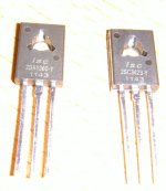
I have attached a photo, ZDR.
Are these fakes?
I bought them from a big, famous German online store recently.
Best regards - Rudi
Are these fakes?
I bought them from a big, famous German online store recently.
Best regards - Rudi
Attachments
Last edited:
Rudi, I,ve just finished doing a little test on the diodes only on the njl0281dg transistors and I,ve discovered that there is a big difference in voltage drops across the diodes and different current levels,,enough so 1 device can cause a problem. I,m going to test other devices I have to see if the same condition occurs.. Evette
Use the diodes with the lowest voltage drop. If this will not work, bypass one of the five diodes with a small Schottky diode. (BATxx type will be fine.) With only four TT diodes bias voltage could be undercompensated. Schottky diodes have negature temperature coefficient and are used in some Sanken SAP devices.
The transistors aren't counterfeit, they're genuine chinese stuff. ISC is a chinese manufacturer and their process could differ from the japanese one.
Don't trow them away. Let's see if we can fix the problem as suggested above.
The transistors aren't counterfeit, they're genuine chinese stuff. ISC is a chinese manufacturer and their process could differ from the japanese one.
Don't trow them away. Let's see if we can fix the problem as suggested above.
Hello Rudi,
Those are the chinese version (some would call it copies) of the Thosiba ones.
I do not know if those can cause any problem but i would not use them for vas.
Regards,
zsaudio
Those are the chinese version (some would call it copies) of the Thosiba ones.
I do not know if those can cause any problem but i would not use them for vas.
Regards,
zsaudio
I have used these transistors in the past and had nothing but problems with them,osc burn outs you name it I could never get them to work right. Evette
Schottky diodes have negative temperature coefficient.... Sorry
I have some 2SC2922 from ISC and they have huge leakage currents.
I have some 2SC2922 from ISC and they have huge leakage currents.
Last edited:
I have used these transistors in the past and had nothing but problems with them,osc burn outs you name it I could never get them to work right. Evette
good to know. that's why i always try to buy orig japanes parts. It's sometimes very hard to find a trustable dealer and you need to pay extra. I started to buy Sanyo video transistors for my diy store, because of OnSemi.
zsaudio
good to know. that's why i always try to buy orig japanes parts. It's sometimes very hard to find a trustable dealer and you need to pay extra. I started to buy Sanyo video transistors for my diy store, because of OnSemi.
zsaudio
- Status
- Not open for further replies.
- Home
- Amplifiers
- Solid State
- Roender's FC-100 prototype and builder's thread