Hello Rudi,
If you have some left stereo boards i buy those and can test it.
I've bought the NJL's from Mouser and look good at matching.
I've several Toshiba trannies too.
Regards,
zsaudio
If you have some left stereo boards i buy those and can test it.
I've bought the NJL's from Mouser and look good at matching.
I've several Toshiba trannies too.
Regards,
zsaudio
Gentlemen,
thank you all for your help debugging the problems I have.
The AMP has 3 NJL0281DG on the positive rail and 3 NJL0302DG on the negative rail.
The integrated thermal track diodes build a chain that looks like this:
Diode of first NJL0281 -> Diode of second NJL0281 -> Diode of third NJL0281 -> Diode of first NJL0302 -> Diode of second NJL0302
The diode of the third NJL0302 is bypassed by layout.
The diode of the second NJL0302 is short currently.
I measured the voltages on the anode and cathode of each diode.
Here are the results:
1st NJL0281 - Anode: 1185 mV, Cathode: 680 mV - Drop: 505mV
2nd NJL0281 - Anode: 680mV, Cathode: 170 mV - Drop: 510mV
3rd NJL0281 - Anode: 170mV, Cathode: -320mV - Drop: 490mV
1st NJL0302 - Anode: -320mV, Cathode: -810 mV - Drop: 490mV
There is no big deviation at all.
Best regards - Rudi
And how big is the voltage across C7 (measured directly)? Are the values of the resistors R5, 6, 41 the right ones?
Last edited:
I am at a loss currently concerning my build.
I measured and measured; everything looks good.
There is a 20 Ohm resistance between any base of a NPN- and any base of a PNP - output-transistor, there is a 16 Ohm resistance between
the base-stopper of any NPN- and the base-stopper of any PNP - output-transistor (between the drivers), ..., and the speaker-output signal
with a 500 Hz sine wave applied to the input does not look bad either.

http://www.abload.de/img/osci00126489.jpg
But I am still not able to activate the 5th diode.
If I try, the minimum voltage drop across an emitter resistor that I can adjust with a 0 Ohm trim-resistor's value, is 45 mV.
Since some oy you suspected the used ISC transistors, I will test them this afternoon.
Best regards - Rudi_Ratlos
I measured and measured; everything looks good.
There is a 20 Ohm resistance between any base of a NPN- and any base of a PNP - output-transistor, there is a 16 Ohm resistance between
the base-stopper of any NPN- and the base-stopper of any PNP - output-transistor (between the drivers), ..., and the speaker-output signal
with a 500 Hz sine wave applied to the input does not look bad either.

http://www.abload.de/img/osci00126489.jpg
But I am still not able to activate the 5th diode.
If I try, the minimum voltage drop across an emitter resistor that I can adjust with a 0 Ohm trim-resistor's value, is 45 mV.
Since some oy you suspected the used ISC transistors, I will test them this afternoon.
Best regards - Rudi_Ratlos
Attachments
Hi Rudi,
I would like to help you ... in order to do that you have to measure the voltage dropped over the following resistors and come back here with the results:
-R19 (91ohm)
-R20 (1k2)
-R15 (150ohm)
-R18 (150ohm)
-R16 (150ohm)
-R17 (150ohm)
-R5 (16ohm)
-R6 (220ohm)
-R41 (220ohm)
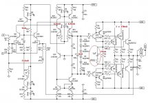
All the above notations are based n the original schematics posted in RMI-FC100 thread.
Kind regards,
Mihai
Thank you for your assistance, Mihai.
Since I have to drive to Hamburg right now, I will come back to you with the values in the late afternoon / evening.
Best regards - Rudi
Since I have to drive to Hamburg right now, I will come back to you with the values in the late afternoon / evening.
Best regards - Rudi
Mihai,
here are my measurements.
The current build:
- Frontend-shunt regulator with 39V ZenerDiode powered by mains directly
- Backend PSU installed after light-bulb tester
- the internal diode of transistor Q27 bypassed by layout
- the internal diode of transistor Q5 short
I measured with one probe head of my DMM connected to GND constantly.
I will therefore give 2 values for each resistor, one value for each side.
R19: -40.69 -39.48
R20: +37.0 +35.7
R15: +39.8 +41.0
R18: +41.0 +39.8
R16: -40.9 -40.6
R17: -40.9 -40.6
R5: -590mV +595mV
R6: +25.0 +25.6
R41: -25.3 -24.8
Best regards - Rudi_Ratlos
Hello rudi,
I simulated the amp with your voltages (frontend +-41V and backend +25,6V -25,3V) and got similar currents (5 NJL diodes are connected).😕
zsaudio
I simulated the amp with your voltages (frontend +-41V and backend +25,6V -25,3V) and got similar currents (5 NJL diodes are connected).😕
zsaudio
Hello ZSAUDIO,
does your simulation include 0R1 or 0R2 emitter-resistors?
I am using 0R2, since my NJL transistors are not as perfectly matched as Mihai's. Mihai has used 0R1 (as far as I know).
Best regards - Rudi
does your simulation include 0R1 or 0R2 emitter-resistors?
I am using 0R2, since my NJL transistors are not as perfectly matched as Mihai's. Mihai has used 0R1 (as far as I know).
Best regards - Rudi
Measure the voltage across R22 in operation. Discharge the power supply, and measure resistance setting of R22. Divide voltage by resistance.
Measure the voltage across R22 in operation. Discharge the power supply, and measure resistance setting of R22. Divide voltage by resistance.
Seeing the voltage dropped over the requested resistors I'm pretty sure that nothing is wrong with the frontend as all the currents are as they should be.
Seeing the voltage dropped over the requested resistors I'm pretty sure that nothing is wrong with the frontend as all the currents are as they should be.
If the voltage across the bias string is a function of current through them and their temperature, and the current is correct, then is the emitter voltage being measured at stable idling temperature, and/or does the output bias vary that much from cold to stable idle temp?
I am new to diyaudio, and would like to thank you for this thread. I cannot contribute too much at this point, but I am learning as you are posting. Thanks for the spice models, eagle files, calculations, details and tips provided along the way. It at least gives me a footing to play with (and learn) and a reference for when it comes time to build. Thanks Mr. Roender for providing a wonderful amp I would like to build, though it is not the original to the 'tee' and Mr. Ratios for the work and providing this opportunity. Also everyone else providing the great information I really appreciate it. I am looking forward to the learning process and the build when it is available.
Gentlemen,
I have been offline in the last 2 hours.
I will now check everything that you proposed and will post the results here.
This may take some time though.
I will use the 4-diode string. Can you confirm, please?
I will also replace the 0R2 emitter resistors to 0R1.
Best regards - Rudi_Ratlos
I have been offline in the last 2 hours.
I will now check everything that you proposed and will post the results here.
This may take some time though.
I will use the 4-diode string. Can you confirm, please?
I will also replace the 0R2 emitter resistors to 0R1.
Best regards - Rudi_Ratlos
Last edited:
Gentlemen,
I will also replace the 0R2 emitter resistors to 0R1.
No. Just leave in the ones you have, and measure voltage across all of them.
- Status
- Not open for further replies.
- Home
- Amplifiers
- Solid State
- Roender's FC-100 prototype and builder's thread


