i have the same .4 reading when testing the other solder pads that are on the other insulators also.
OL and 0 ohms are exact opposites. OL means that there is a broken/open connection. 0 ohms (or whatever your meter reads when you touch the probes together) means that there is a direct connection.
Go back and try to find the direct connections between the SMD resistor and the pads for the jumper.
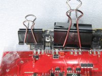
To get the jumper soldered back to the insulator, you'll need to use the torch. Use a black binder type paper clip (see attached for an example) to hold the output transistor in place.
Completely remove the jumper from the main board and clear the solder through-holes for the jumper (on the main board).
If the jumper is bent, reform it to lay properly on the insulator and have the legs fit into the through-holes. Make sure that the insulator is at the proper angle when checking the fit of the jumper.
With the binder clip in place, heat the insulator with the torch until solder flows freely onto one of the solder pads for the jumper. Place the jumper on the tinned pad and heat it with your soldering iron. It should solder on relatively easily if you heated the insulator well and didn't wait too long to solder the jumper. Solder the other two legs of the jumper to the insulator.
Place the board in the heatsink and screw the insulator to the wall of the heatsink. Solder the three legs of the jumper to the main board. Remove the board and solder them from the other side if the solder didn't penetrate the vias fully.
If this is the only thing that's changed from the last time it was powered up, power it up via a 30 amp fuse. Does it blow the fuse?
Go back and try to find the direct connections between the SMD resistor and the pads for the jumper.
To get the jumper soldered back to the insulator, you'll need to use the torch. Use a black binder type paper clip (see attached for an example) to hold the output transistor in place.
Completely remove the jumper from the main board and clear the solder through-holes for the jumper (on the main board).
If the jumper is bent, reform it to lay properly on the insulator and have the legs fit into the through-holes. Make sure that the insulator is at the proper angle when checking the fit of the jumper.
With the binder clip in place, heat the insulator with the torch until solder flows freely onto one of the solder pads for the jumper. Place the jumper on the tinned pad and heat it with your soldering iron. It should solder on relatively easily if you heated the insulator well and didn't wait too long to solder the jumper. Solder the other two legs of the jumper to the insulator.
Place the board in the heatsink and screw the insulator to the wall of the heatsink. Solder the three legs of the jumper to the main board. Remove the board and solder them from the other side if the solder didn't penetrate the vias fully.
If this is the only thing that's changed from the last time it was powered up, power it up via a 30 amp fuse. Does it blow the fuse?
okay so s there a problem with a connection between the smd resitor and the insulator. i am not quite understanding if i am fixing something.
or if nothing is wrong?
or if nothing is wrong?
Missing attachment from last post.
This is simply an example of the types of clips and the placement. This amp was being repaired and was simply convenient to use. The tape (difficult to see) is being used to keep the heatsink compound at bay. You would NOT have tape applied when heating the insulator.
This is simply an example of the types of clips and the placement. This amp was being repaired and was simply convenient to use. The tape (difficult to see) is being used to keep the heatsink compound at bay. You would NOT have tape applied when heating the insulator.
Attachments
You need to confirm the connection between the solder pads and the terminals on the SMD transistor.
The rest was telling you how to solder the jumper back in place.
The rest was telling you how to solder the jumper back in place.
they all test good, but i have found out that i have to fond the actual trace where it starts @ the pad, and touch my provbe to it. one is actually slightly peeled back, but i hope i slight bit of solder bidged back to it will work.
and what about the other unsoldered jumper on the other side of the output bord do i need to conform connection to smd transistor, and if all is good, solder back on?
I don't know about the unsoldered jumper.
Repair this jumper and if there is still a problem, we'll look at the other jumper.
After soldering the jumper, confirm that you don't read anythign near 0 ohms between any pin of the jumper and the MEHSA insulator.
Repair this jumper and if there is still a problem, we'll look at the other jumper.
After soldering the jumper, confirm that you don't read anythign near 0 ohms between any pin of the jumper and the MEHSA insulator.
If you touch your meter probes to adjacent solder pads on the MEHSA insulator, what is the resistance?
If you read 0.6 ohms between adjacent traces, the solder pads have likely been lifted. Confirm this by measuring the resistance from the back of the insulator to each of the jumper's solder pads on the insulator. Do you read near 0 ohms?
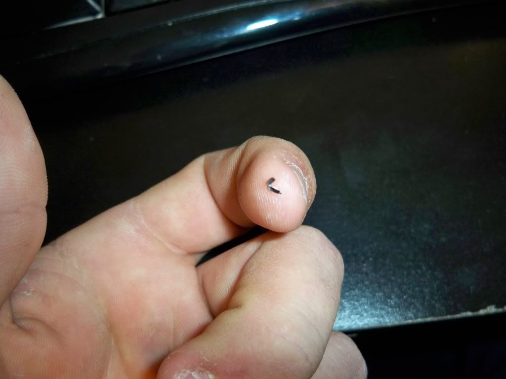
alright went hunting for the metal shaving looking thing and found it. this came off while soldering the pads.
On the other channel, find the 2 terminals of the jumper that connect to the top and lower right legs of the SMD transistor. I think they'll be legs 1 and 2 of the jumper (left to right). Confirm this.
unfortunately they are buried under the output transistor. and i cannot see them. would the pin out of the one i am currently fixing suffice?
- Status
- Not open for further replies.
- Home
- General Interest
- Car Audio
- rockford fosgate t15002 amp troubles