seems some voltages are either fluctuating or flashing now. light stopped double flashing, and 30 amp fuse blows now, have to resort to the 200am fuse it came with.
U3
Pin 1: 4.6
Pin 2: 17.5
Pin 3: 18
Pin 4: .17
Pin 5: 2.38
Pin 6: 4.73
Pin 7: 4.96
Pin 8: .589
Pin 9: 5.4
Pin 10: 1.5
Pin 11: 1.5
Pin 12: .004
Pin 13: .5
Pin 14:4.94
U3
Pin 1: 4.6
Pin 2: 17.5
Pin 3: 18
Pin 4: .17
Pin 5: 2.38
Pin 6: 4.73
Pin 7: 4.96
Pin 8: .589
Pin 9: 5.4
Pin 10: 1.5
Pin 11: 1.5
Pin 12: .004
Pin 13: .5
Pin 14:4.94
Are the bias potentiometers near the output transistors in the fully counter-clockwise position?
If I'm not mistaken, you stated that none of the outputs were getting hot. Is this still true? Did you notice anything heating up when you were measuring the voltages on U3?
the only heat is on channel 2. now after about 10 minutes of testing they are WARM. i do notice that channel ones outputs aren't warm AT ALL. they are cold. i felt this was odd. all outputs test good with meter.
I'd like to use a current limiter in the B+ line but it would probably be too costly. If the outputs only get warm after 10 minutes, it may be safe to continue testing. Power up the amp and measure the DC voltage (down to the millivolt, 0.000v resolution) across each of the 0.1 ohm resistors in the repaired channel. (place the probe on each end of the resistor when measuring the voltage. Post a list of the voltages, re-check to see if they change more than ~10% from the initial readings. Polarity (+/-) isn't important here. Only be concerned with the value.
weirdly, testing some of the voltages changed the frequency that of the led flashing.
all voltages were flashing from 000 to posted voltage. and some were - voltages.
1:.007
2:.007
3:-.008
4:-.007
5:-.006
6:.007
7:.017
8:.016
9:.015
10:.017
11: .013
12:.019
channel one showed NO voltage on nearly all resistors but maybe 2.
all voltages were flashing from 000 to posted voltage. and some were - voltages.
1:.007
2:.007
3:-.008
4:-.007
5:-.006
6:.007
7:.017
8:.016
9:.015
10:.017
11: .013
12:.019
channel one showed NO voltage on nearly all resistors but maybe 2.
It's strange that half have ~2x the current through them. I'm assuming that all of these resistors are new.
With no power applied and no speaker load connected, what's the resistance across the speaker terminals for one this channel? If you can't get a steady reading, clamp the probes in the speaker terminals.
With power applied, what's the DC voltage on this channel?
With no power applied and no speaker load connected, what's the resistance across the speaker terminals for one this channel? If you can't get a steady reading, clamp the probes in the speaker terminals.
With power applied, what's the DC voltage on this channel?
actually those are the resistors on the 36p15's. im not sure if thats normal or not. but there are new and old on both channels.
Can you post some high resolution photos showing the entire set of MEHSA insulators for the defective channel?
i could not get my pics to show on thread. you should be able to view them via this link.
Pictures by grandam88 - Photobucket
Pictures by grandam88 - Photobucket
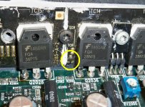
For Q2036, make sure that you don't read anything near 0 ohms between the three legs of the transistor and the the three legs of the 3-legged jumper to the right of the transistor. Check all combinations.
Also confirm that you have three 0 ohm connections between the terminals of the surface mount transistor just to the left of Q2036 and the 3-legged jumper. none of these should be shorted together. Confirm that none are.
Also confirm that you have three 0 ohm connections between the terminals of the surface mount transistor just to the left of Q2036 and the 3-legged jumper. none of these should be shorted together. Confirm that none are.
It's possible. Sometimes the insulating coating gets damaged and the new transistors short to those traces.
on the the q2036 i got nothing all good readings but on one leg got an OL and couldn't get a reading.
on the second test, testing for ohms to surface mount transistor, i got readings in the m ohm range. that's if the link i posted is the surface mount transistor.
please confirm i am testing the right component.
100_0878-1.jpg picture by grandam88 - Photobucket
on the second test, testing for ohms to surface mount transistor, i got readings in the m ohm range. that's if the link i posted is the surface mount transistor.
please confirm i am testing the right component.
100_0878-1.jpg picture by grandam88 - Photobucket
- Status
- Not open for further replies.
- Home
- General Interest
- Car Audio
- rockford fosgate t15002 amp troubles