With a short wire jumper, connect the solder pads for leg 1 and leg 2 of the jumper for the repaired channel. Clamp the amp back to the heatsink and power it up via a 15 or 20 amp fuse (30 if you don't have those) amp fuse. Does the fuse blow.
The SMD transistor is the bias transistor. It's important for the proper operation of the amp.
The SMD transistor is the bias transistor. It's important for the proper operation of the amp.
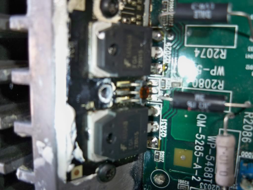
heres a picture. if you look closely, the pins are separated from the insulator.
this is also for channel 2
also how am i supposed to attach this wire. i cannot solder to the either of the 3 solder pads on the insulator
From the tests that you've done, there are no pads left to solder to. I don't know about this second one. It may not be an issue. Clamp everything back down as it's supposed to be and see if it blows the fuse.
so "dont" do the short jumper wires? what if i bypass the traces, and temporarily solder a wire from each leg, to its corresponding spot on the transistor.
If, on the good channel, the two points (connected by the red line) were connected to the top and lower right terminals of the SMD transistor on the MEHSA insulator, connect the points indicated by the red line (on the repaired channel) together with a short wire. Do NOTHING to the good channel. Don't concern yourself with any other jumpers at this time.
Attachments
alright amp powers on with 30 amp fuse, and stays on without protect. does blow 15 amp fuse though.
what next?
what next?
Measure the DC voltage across the 0.1 ohm resistors again. You don't need to post all of them. If all of the 28N are the same, post the average. If all of the 36P are essentially the same post the average. Check the ones in the other channel. They should all be at ~0.000 if the bias pot is fully counter-clockwise.
Also check the DC voltage across the speaker terminals.
Also check the DC voltage across the speaker terminals.
every single .1 ohm resitor measures 0 voltage.
channel 1 voltage is -.012(neagative)
channel 2 is .002
channel 1 voltage is -.012(neagative)
channel 2 is .002
Connect a speaker to the repaired channel to see if it will produce clean audio. Don't drive it hard yet and just run it for a short time (especially if you don't have fresh heatsink compound between the insulators and the heatsink). Have all transistors tightly clamped to the heatsink when you do this. Watch the speaker and be prepared to shut it down instantly if the speaker pulls in or pushes out.
also, as far as the other jumper on channel two, it looks kind of like a smd resistor, but its unmarked. i have a feelings its a thermistor as i have had a hard time seeing one anywhere else. and if i apply a small amount of heat the resistance changes.
Last edited:
Yes. It's a thermistor. There are likely 2 or 3 on the MEHSA insulators.
Tomorrow, power up the amp and let it idle (no RCAs and no speakers). Does the power supply end of the amp begin to heat up after about 10 minutes?
Does anything else begin to heat up?
The 15+ amps of idle current is much too high. The two tests above may help narrow it down.
There are other issues we'll have to deal with but it's good to see that the audio section of the amp seems to be generally healthy.
im happy the audio section of the amp is working well. tomorrow i will let amp idle for a while and see what happens.
is it possible to place a different package type transistor to where the three legged jumper used to be? or am i going to have to replace or repair the existing mehsa boards.
could i replace the thermistor with a different package thermistor directly into the whole of the three legged jumper on the board?
I'll have to look into the thermistor issue, but not now. It appears that there are 2 thermistors on the MEHSA insulators. One connected to J5 and the other connected to J6.
I thought about using a transistor in a TO-92 case (like the KSC945C) but it would require a bit of testing to see if it was compensating properly. The alternative would be to replace the MEHSA insulator but it would likely have the outputs on it which wouldn't match the other outputs (the ones with the same part number). That would require replacing them for the best reliability. That's assuming that it's still available.
I thought about using a transistor in a TO-92 case (like the KSC945C) but it would require a bit of testing to see if it was compensating properly. The alternative would be to replace the MEHSA insulator but it would likely have the outputs on it which wouldn't match the other outputs (the ones with the same part number). That would require replacing them for the best reliability. That's assuming that it's still available.
- Status
- Not open for further replies.
- Home
- General Interest
- Car Audio
- rockford fosgate t15002 amp troubles