yeah this insulator only holds 2 output fets, probably making it even harder to find.
i just cannot believe the condition this amp is in. the b+ terminal was basically falling out. two of the blade connectors for the jumper wires to connect the v+, v-, and ground, were so loose i could pull them out of the board with my fingers.
i bought this amp and used it all of 2 days before it took a dive, was subjected to under voltage. The under voltage was probably due to the b+ terminal starving the amp of power and the bad connections to the output side from the jumper wire blades.
i have fixed all the loose connections since, and hope things go better when my amp is 100% fixed. i kind of have a new appreciation for "taking care" of an amplifier as i see the time and money it takes to fix one.
alright, i let the amp run for about 20 minutes. no temps above 100 degrees. i am using a infrared hand held thermometer. the hottest item was a lm317t @ 95-100 degrees.
Were the MEHSA insulators clamped to the heatsink?
Did the power supply end of the heatsink get warmer than the audio end of the heatsink?
Did the power supply end of the heatsink get warmer than the audio end of the heatsink?
mehsa boards were screwed down to heatsink.
the power supply side heatsink reached about 100F, the output side didn't get any hotter than about 80 degrees.
the power supply side heatsink reached about 100F, the output side didn't get any hotter than about 80 degrees.
Is the DC voltage on the center legs of the rectifiers greater than the working voltage printed on the rail capacitors (likely the largest capacitors in the amp)?
You'll need to order a substitute bias transistor. The 512-KSC945CGTA from Mouser should work. Order a few extras.
If you don't have any heatsink compound, order some when you order the transistors.
I believe that there are other problems causing it to blow a 15 amp fuse but I can't think of any other tests that you could do to determine where the problem is. If I'm not mistaken, you stated that it didn't blow instantly when powering up the amp. This would seem to indicate that the excessive current draw is constant. The fact that the heatsink on the power supply go to 100° at idle is also an indication that there is a problem.
the 15 amp fuse blows as soon as remote voltage is applied. i can try another time to confirm.
i have heat sink compound but may order more if mousers price is good.
so i don't have to make multiple orders from mouser, what should i do about the thermistor? can i replace with a thermistor that can fit whee the jumpers r now?
i notice on the jumpers that r desoldered on the mesha containing te thermistor, there is a white layer on the contacts(maybe the seperation between mesha and solder pad, and on back of jumper legs a small layer appearing to look like the solder pad.
I'll need photos of the thermistor and the jumper you're referring to.
Try this, power up the amp with a 15 amp fuse in the holder and a short wire jumping across the fuse. Allow the amp to power up and remove the jumper, leaving the fuse alone to pass current. Does the fuse blow?
Try this, power up the amp with a 15 amp fuse in the holder and a short wire jumping across the fuse. Allow the amp to power up and remove the jumper, leaving the fuse alone to pass current. Does the fuse blow?
alright using a jumper wire across fusible link worked, removing it after amp has powered up.
also i have a VERY VERY faint protect light. dunno what it is, but amp is working, so i don't think it in protect.
its the orange light in the photo
also i have a VERY VERY faint protect light. dunno what it is, but amp is working, so i don't think it in protect.
its the orange light in the photo
The dim amber LED is common for the Rockford amps that use the protection circuits like the ones used in your amp. If it illuminates for a fault, it will be much brighter.
OK, the current draw may not be excessive. What type of fuses are you using for testing?
OK, the current draw may not be excessive. What type of fuses are you using for testing?
in the last test i used a 15amp fuse. i have alot of those. but nothing smaller. and i will be taking pics of thermistor shortly
ato 15 amp copperbussman.
heres pics of thermistor and jumper next to it. you can see in the center (barely) a solder pad(with solder). on solder pads left and right of that, white.
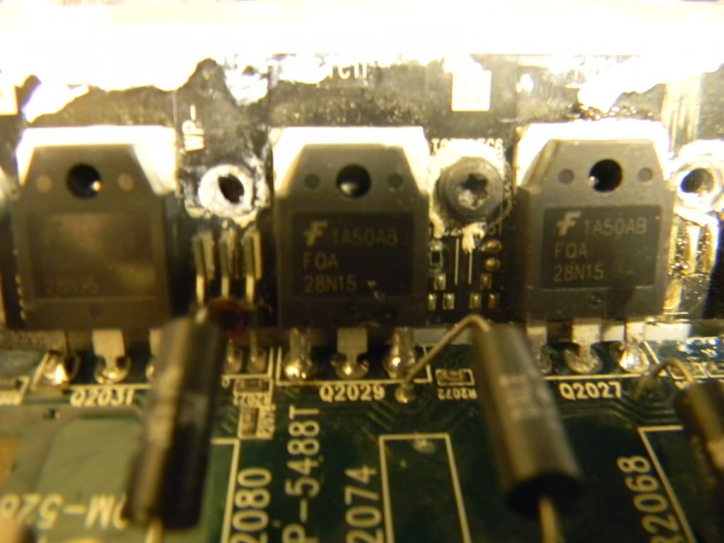
heres pics of thermistor and jumper next to it. you can see in the center (barely) a solder pad(with solder). on solder pads left and right of that, white.
If the solder pads have been damaged as they were on the other MEHSA insulator, you could use a leaded/through-hole type thermistor. Measure the resistance across the thermistor when the amp is at ~70° F. Order an NTC thermistor with that resistance value. You'll remove the jumper completely and solder the thermistor's leads in the outer through-holes.
For this and the bias transistor, you'll apply a generous amount of heatsink compound between the component and the MEHSA insulator and use the fiberglass piece to hold them tightly against the insulator. You'll need to ensure that the leads of either component do NOT contact the insulator.
For this and the bias transistor, you'll apply a generous amount of heatsink compound between the component and the MEHSA insulator and use the fiberglass piece to hold them tightly against the insulator. You'll need to ensure that the leads of either component do NOT contact the insulator.
alright sounds good, i will send you a link of the thermistor i plan on buying when i find it on mouser. also do u still feel there is excessive amperage on power side?
thanks
thanks
I'm not as concerned about excess current draw now but this is the first amp that I've seen that wouldn't power up through a 15 amp ATC type fuse. It may be due to the larger wiring in the vehicle, compared to that on the workbench (less resistance allowing higher surge current).
- Status
- Not open for further replies.
- Home
- General Interest
- Car Audio
- rockford fosgate t15002 amp troubles