I never intended for the final amp to have different values for R5 and R7. OTOH, I may yet set them to different values, and inject a current into the emitter of Q30 to zero the amp's DC offset.
What I typically do for folded-cascode circuits is add a current source above R5/R7, and connect the collectors of a LTP (with its own current sink) across the emitters of Q6. One of the LTP bases is connected to the servo opamp (via an RC network to attenuate undesirable components), and the other LTP base is connected to ground. Works quite well.
kind regards, jonathan
Great idea, Jonathon. Also, it would not fight the autobias circuit, since it's adding a differential current and the autobias is adding current to both sides. Let me ponder that.
I'm not sure I need current sources above R5/R7. Just the differential adustment at the Q6 emitters should do it. I will have to boost the current a bit, to feed the LTP, but it needs almost no current at all to balance the amp. In fact, the autobias servo will automatically adjust the sources to have enough current.
I'm not sure I need current sources above R5/R7. Just the differential adustment at the Q6 emitters should do it. I will have to boost the current a bit, to feed the LTP, but it needs almost no current at all to balance the amp. In fact, the autobias servo will automatically adjust the sources to have enough current.
Sharing SLABS Layout
Hi Russel, I'm going with the +/-15V then. I agree the TO-220 are a safe bet. The SOT-89 in my previous layout was a bit pushing considering the 2/499 "telescoped" output transistor dynamic Ic will go through Q12 as well on top of the TL084 consumption.
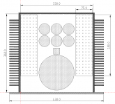
Heatsink got replaced with Aavid-57202B0, same exact stuff but at 1/2 price.
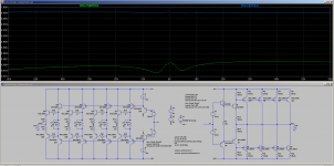
KiCAD's hi-res rendering is quite impressive.

Attached below is the entire layout folder, Including the schematic, the layout, the Gerber/Drill, and the 3D model of the heatsink.
Hi Russel, I'm going with the +/-15V then. I agree the TO-220 are a safe bet. The SOT-89 in my previous layout was a bit pushing considering the 2/499 "telescoped" output transistor dynamic Ic will go through Q12 as well on top of the TL084 consumption.
Heatsink got replaced with Aavid-57202B0, same exact stuff but at 1/2 price.
KiCAD's hi-res rendering is quite impressive.
Attached below is the entire layout folder, Including the schematic, the layout, the Gerber/Drill, and the 3D model of the heatsink.
Attachments
The extra current source can add some PSRR, but without should also work (and will help with voltage headroom).
Right, the amount of current through the front end and folded-cascode section should be increased a little to compensate for the amount diverted by the LTP.
kind regards, jonathan
Right, the amount of current through the front end and folded-cascode section should be increased a little to compensate for the amount diverted by the LTP.
kind regards, jonathan
I find that I am still fussing with two-pole Miller compensation (TPMC). I would like to see a 6dB reduction in THD at 20 kHz, while maintaining at least 60 deg of phase margin and 6 dB of gain margin.
The gain of the FC stage is so high that TPMC cannot fully stabilize it, I am left with a resonant peak at around 8 MHz, which would make this amp an oscillator. I can do one of two things:
The output stage is really well optimized for linearity at low frequencies right now, but it could be better at high frequencies. I think any kind of boosted gain option for the output stage, such as making it a CFA, or using complementary feedback pairs (CFP) will also show much lower linearity at 20 kHz. Still, I am open to suggestions. The brute force way to get high power linearity is to run class A. With 100mA/output transistor, the output stage is class A up to about 2.5W@8ohms. Class A at 10W would require 200mA bias/output transistor. That's 50W dissipation on the heatsink vs. 100W. This might be worth doing.
The gain of the FC stage is so high that TPMC cannot fully stabilize it, I am left with a resonant peak at around 8 MHz, which would make this amp an oscillator. I can do one of two things:
- Put a phase lag cap to GND from the amp's negative input. I tried this option. This cap hurts phase margin, which dropped to 55 deg. It only gave about 2 dB of THD improvement at 1W-20 Khz, about 1 dB at 10W, and actually hurt 20 kHz THD at 100W and 200W. This option behaves badly with large signals.
- Partially compensate with TPMC and partially with C from FC output to GND. This option greatly reduces the effect of the TPMC, but still allows the amp to have good PM and GM. This is where I am right now. I am only getting about 1 or 2 dB improvement in linearity at high frequency.
The output stage is really well optimized for linearity at low frequencies right now, but it could be better at high frequencies. I think any kind of boosted gain option for the output stage, such as making it a CFA, or using complementary feedback pairs (CFP) will also show much lower linearity at 20 kHz. Still, I am open to suggestions. The brute force way to get high power linearity is to run class A. With 100mA/output transistor, the output stage is class A up to about 2.5W@8ohms. Class A at 10W would require 200mA bias/output transistor. That's 50W dissipation on the heatsink vs. 100W. This might be worth doing.
Hi Russell,
This is one of the very best threads on amplifiers in a long time!
Especially the autobias part intrigues me since I've been pondering about the same for quite a while. Interesting that my thoughts are very similar to your implementation.
But for now, if I may, I'd like to suggest a different output stage for this amplifier.
You could call it a 2EF stage with helper current dumping transistors, or a variant of a CFP stage. The trick to achieving low distortion is to make sure the drivers operate in class-A while the output transistors operate in optimal class-B. Then the open-loop distortion becomes 6-20dB less than a optimally biased 3EF output stage. The wing-plot shows this quite well.
I wasn't the first to consider such output stage, it has been discussed in a thread on this forum before, but now I can't find it. And I believe that thread was again based on an article.
The reason why this isn't more popular is that it is nearly impossible to keep a stable quiescent current in the output transistors with a normal thermal feedback Vbe multiplier due to the gain between the idle currents in the driver and the output transistor. However it fits perfectly with your autobias that senses the current in the output transistors on positive and negative rails.
I hope you will try it out in you sim and let us know your results and thoughts on this.
Br,
ojg
Attachments
Hi ojg,
I looked at that exact variation on the OPS a few months ago, when I was deciding on which topology to use. I decided to use the autobias circuit later, and did not rethink my OPS choices.
You are correct that it is a lot more linear than the 3EF. As I recall, I did move away from it because of the difficulty of keeping a stable bias. I think you are right that the autobias circuit can do the job. At your suggestion, I think I will try it again. I have to check two things:
If (1) is true, and (2) shows significant improvement, I will likely make that change. It will be a week or more before I can take a look at it again, because work has me really busy right now.
I looked at that exact variation on the OPS a few months ago, when I was deciding on which topology to use. I decided to use the autobias circuit later, and did not rethink my OPS choices.
You are correct that it is a lot more linear than the 3EF. As I recall, I did move away from it because of the difficulty of keeping a stable bias. I think you are right that the autobias circuit can do the job. At your suggestion, I think I will try it again. I have to check two things:
- The stability of the autobias loop with the extra gain. I think it will be fine.
- The linearity of the EF+CFP at high frequencies
If (1) is true, and (2) shows significant improvement, I will likely make that change. It will be a week or more before I can take a look at it again, because work has me really busy right now.
My pleasure, Russell. Fun to do some armchair engineering on someone else's project once in a while 🙂
I tried a version with individual KSA1381 drivers for each output transistor, but interestingly the linearity was worse, the wing-plot was more asymmetric leading to higher second order distortion. This could be due to the spice models of course, but I generally trust Cordell's models.
I found the post where this stage was discussed previously:
https://www.diyaudio.com/forums/sol...amp-modulated-class-output-5.html#post5671657
I checked the service manual of the Nakamichi PA-5, and sure enough it uses this topology. Much lower gain though, and with a Vbe multiplier with a thermistor in it. Would be interesting to do a thermal simulation of this.
Br,
OJG
I don’t think the thermal tracking of several of my spice models is any good. Typically, I have to sort that on the bench.
Baker clamp
Just wondering, why don't you use a "flying" Baker clamp when you are using a "Diamond" OPS?
Stein
Just wondering, why don't you use a "flying" Baker clamp when you are using a "Diamond" OPS?
Stein

I just ordered 6 of this chassis through Alibaba. I'll use one to house dummy resistor loads, and then I will build 5 amps. At least 2 will be whatever this design turns out to be. After that, I'll probably do a blameless. OTOH, the Wolverine amp is shaping up really great over at
DIYA store "Wolverine" (Son of Badger) .... suggestions ??
Anyway, I spent $811, so now I'm committed.
DIYA store "Wolverine" (Son of Badger) .... suggestions ??
Anyway, I spent $811, so now I'm committed.
Attachments

Nice chassis’s Russell, I have the same one in my “watched” list also😉
What size trafo do you plan to use? And what type of Softstart circuit?
What size trafo do you plan to use? And what type of Softstart circuit?
I tentatively have a Avel Lindberg 800 VA transformer picked out.
As for soft start circuits, I definitely will use one. No specifics yet.
As for soft start circuits, I definitely will use one. No specifics yet.
Ok, thanks for the info.
I have an 800va Toroidy in my stash, but the secondaries might be a bit low at 45vac.
I have an 800va Toroidy in my stash, but the secondaries might be a bit low at 45vac.
Last edited:
Actually, that's the same one. That will give you a 63V rail before sag.
I haven't really looked at how much sag the amp will have, but simulations are getting within 1.5V of the rails, and I need +/-57V to get 200W. Will I have 4V of sag? What is funny is that I don't have much experience driving amplifiers from the AC line. In the 1990s, all my production amplifiers were fed from regulated switching power supplies, powered from 12 to 14.4V DC. I designed the Kicker amplifiers, back in the day.
I have found that inverting the signal to one of the channels helps a lot with sag. To do that, I'll need an op-amp front end, like the OPA1642 or OPA1612. I might as well add differential XLR input while I'm at it.
The real question is how will I get +/-70V for the IPS and pre-driver. I'm still pondering it. Probably a 2nd transformer and separate linear regulator for each channel. A boost converter from the main rails is also a possibility.
I simply had not considered it. I'll try it and see if it makes any difference. I can't do anything with it for about a week. I'm really busy at work.
Is this what you have in mind? (diodes D5, D1, D2)
Hi Russel
Yes, something like that.
I dont use D1, but my "diamond" is a bit different.
I haven't simulated your amplifier, but I think that you are "killing" a lot of gain by your compensation.
Stein
- Home
- Amplifiers
- Solid State
- RK-Auto200W Amplifer