Indeed your pcb is very beautiful and compact. The reason I made these small changes was so that I didn't have to use extra power resistors to gather current information. Another reason was that the power supply was simpler. In my opinion, no special circuits are needed to discharge the capacitors. The way I drew them at the start, the optocoupler is blocked and starts to run late so that the idle current through the power transistors gradually increases. ic4 I think lm4562 and ic4 tl082 are enough. I think that having fewer parts, the pcb can be made even more compact. This time I also drew the power supply. It can be seen that the voltages are also obtained here from the power supply of the amplifier by bootstrap.
Attachments
It's great to see an alternative implementation of the autobias circuit being developed. I think both solutions have their merits.
For a new amplifier like Russells it make sense to implement it like he did. Akosboros implementation is great because it can be retrofitted to any normal amplifier with EF output and Vbe multiplier with just a few connections. And it can be removed completely and the amplifier would still work.
Russells version will be easier to measure and troubleshoot since it is referred to true ground. akosboros floating virtual ground makes this a bit harder.
Some might be scared to see the speaker output as a ground bus with all kinds of currents terminating into it. It will depend on the feedback of the amplifier itself to correct for this current. To ease those worries the output of the amplifier could be buffered with an opamp or similar to create the virtual ground and return those currents to the rails.
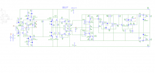
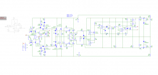
Indeed your pcb is very beautiful and compact. The reason I made these small changes was so that I didn't have to use extra power resistors to gather current information. Another reason was that the power supply was simpler. In my opinion, no special circuits are needed to discharge the capacitors. The way I drew them at the start, the optocoupler is blocked and starts to run late so that the idle current through the power transistors gradually increases. ic4 I think lm4562 and ic4 tl082 are enough. I think that having fewer parts, the pcb can be made even more compact. This time I also drew the power supply. It can be seen that the voltages are also obtained here from the power supply of the amplifier by bootstrap.
Thank you for the comment on the SLABS layout 🙂.
By tying C55 to the positive rail instead, as shown in your full schematic, you do have a soft start to the idle current in the output stage.
Using bootstrapping is a smart way to save a floating power supply. I really hope it turns out working well.
Perhaps a common concern about a bootstrapped supply is its behavior when the amp output swings towards the rails. The bootstrapping capacitors can get discharged and the supply starved for a short moment, especially when powerful bass signals hit. I would vigorously simulate the circuit at extreme signal conditions and load conditions (phase angles), although your design may have taken these conditions into consideration and have had them well covered.
Whichever implementation you take I wish you success in experimenting and proving the bias-servo concept working in real world. I could have moved forward with building Russell's SLABS, but had to put off busying between day job and a DAC project.
Beautiful layout!
Do
Thanks! My problem with KiCAD or other modern layout tools is that, PCBs don't look that good at all coming back from a board shop 😀
I put a 56u capacitor because that's why I have it. However f = 1000000 / (2 * 31.14 * 680 * 56) = 4.18 Hz is small enough. Through the bootstrap the 4 ohm load resistance will be in parallel with 680 ohm / 2 and its effect is insignificant. I have attached the simulation in MicroCap.
Attachments
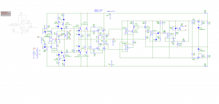
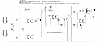
Looking more closely at the diagram I saw that it is not necessary for the bottom of the controlled current generator but only a repeater configuration is sufficient. This is because we are only interested in the sum of the two currents and we are not interested in the value of each current. It simplifies the scheme. After that I removed the comparator transistors, his place being taken by the second tl072 from the capsule. It is possible because the input to tl072 is with jfet and has high input impedance and does not affect the voltage on C54. And so the scheme is simplified even more.
Attachments
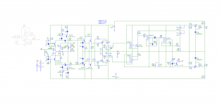
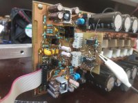
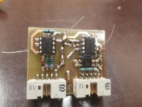
I finalized the scheme and made a test plate. In my opinion it works very well. I attached it to an amplifier built by me recently that had the connection terminals for an autobias. We matched the currents through the final transistors to about 180 mA so that at the input we have about plus-minus 39 mV. Having six irfp240 / irfp9240 transistors the idle current is about 1 A. I would like to hear opinions, criticisms, observations about this autobias.
Attachments

It's clever, I like it.
I would have to see if the floating nature of the circuit affects its performance, as well as the performance of the amp. My initial impression is that it should be OK.
--Russell
Indeed your pcb is very beautiful and compact. The reason I made these small changes was so that I didn't have to use extra power resistors to gather current information. Another reason was that the power supply was simpler. In my opinion, no special circuits are needed to discharge the capacitors. The way I drew them at the start, the optocoupler is blocked and starts to run late so that the idle current through the power transistors gradually increases. ic4 I think lm4562 and ic4 tl082 are enough. I think that having fewer parts, the pcb can be made even more compact. This time I also drew the power supply. It can be seen that the voltages are also obtained here from the power supply of the amplifier by bootstrap.
I would have to see if the floating nature of the circuit affects its performance, as well as the performance of the amp. My initial impression is that it should be OK.
--Russell
Thanks for the continued interest in my amp design, and particularly the autobias circuit. Aksoboro's implementation is nice, but for my design, I'll stick with what I have.
Work is crazy for me right now. I'm trying to do an extremely high speed RF A/D converter. Poring through IEEE papers for architecture ideas and trying to innovate a couple of my own. The whole amp project got started in the Covid shutdown, while I was waiting for my previous IC to come back from the fab.
My feelings won't be hurt if someone picks this up where I left off. My original curiousity was how good an amp I could make with a single gain stage (folded cascode = 1 gain stage). The answer is a damn good amp. The other answer is that the classic "blameless" amp with two gain stages has an edge over this, along with more flexibility for 2-pole and output inclusive compensation to deliver the very highest overall linearity.
Still, I think I will eventually build this one, even if I have to wait until I retire.

hi
Everything tells me, that AD797 is not only a very good operational amplifier
The topology used has got to be something extremely good!
Using only the simplified schematic from Analog Devices datasheet
I get some extraordinary simulation results.
(And I am used to see a few good figures, from my own circuits. Using same transistors.)
===============================
A few details from me, for those who want to try to make a better AD797 Clone.
... but I am not sure anyone could do this better than myself
... maybe get some similar results, but not better, I doubt.
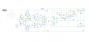
My circuit...
Everything tells me, that AD797 is not only a very good operational amplifier
The topology used has got to be something extremely good!
Using only the simplified schematic from Analog Devices datasheet
I get some extraordinary simulation results.
(And I am used to see a few good figures, from my own circuits. Using same transistors.)
===============================
A few details from me, for those who want to try to make a better AD797 Clone.
... but I am not sure anyone could do this better than myself
... maybe get some similar results, but not better, I doubt.
My circuit...
- lineup
- Replies: 96
- Forum: Solid State
I saw it on this post, cheers!
#156,Power_Amp_200W.asy
You need to change line 15 "Kinder\Documents\Audio_Designs\Circuits_PCBs\Power_Amp_200W\Simulation\Power_Amp_200W.net" to "SYMATTR ModelFile Power_Amp_200W.net" to simulate.
Last edited:
- Home
- Amplifiers
- Solid State
- RK-Auto200W Amplifer