HTTP 301 This page has been moved
HTTP 301 This page has been moved
https://www.audiolabga.com/pdf/2SA1016.pdf
https://www.tme.eu/Document/c83f345465c6e708cfe140e3962fa171/2SA1587.pdf
https://www.mouser.com/datasheet/2/408/2SC4117_datasheet_en_20201120-1916390.pdf
hth, jonathan
PS. The first two links are valid, even though they are being displayed in a manner which suggests otherwise.
Last edited:
Hey Russell,
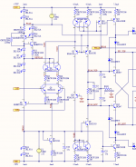
Another suggestion is using a 100ohm series resistor for Q2 emitters. I know member Bonsai mention it was required in one of his amp designs to tame an oscillation.
Rick
Rick,
This post has come back to haunt me. For the past couple of weeks, I was seeing oscillation in my slew rate sims. 105V/us slewing, then 20V pk-pk oscillation at 750kHz. I thought it was maybe the OPS, but nothing I did there made any difference. I began to think it was a numerical error in SPICE, but experience has taught me better.
Finally, I started looking at the bias leg, and even with PCAS and NBIAS set with ideal 2.55V sources, I still had oscillation. Finally, I put 499 ohm in series with each Q2 emitter, and that fixed it. There has to be enough R to begin to limit slew rate. 412 ohms still oscillates at 20V, 422 ohms has no oscillation.
It is weird because I haven't seen anything like it, and because it was not doing it before the beginning of April. I have measured slew rate before. It is clearly a large signal phenomenon, triggered by reaching max slew rate, where 1 side of the LTP runs dry. I am going to investigate a way to fix it other than saturating the high current side.
Attachments
Last edited:
Hi Russell,
I am following along quietly.
The oscillatory ghosts have reared their ugly heads 🙂
We used 100ohms in the DH-220C design. Yes it is weird your design is so sensitive to a small value change. I wish I knew enough to give you some guidance or explanation, but you are far above my design/analysis ability, so I am of little help, sorry.
I was going to comment on the list of EIAJ bjts presented to you, some of which were long obsolete, wondering why recommend or spec an obsolete part. If you use a sot-23 or sc-70 footprint, you have lots of options so not such a big deal.
Good luck
Rick
Hi Russell,
I was going to comment on the list of EIAJ bjts presented to you, some of which were long obsolete, wondering why recommend or spec an obsolete part. If you use a sot-23 or sc-70 footprint, you have lots of options so not such a big deal.
Rick
It's fine. I always check availability before placing. For small signal devices, I've been defaulting to Nexperia. It seems like they have better models for those devices not in Bob Cordell's model file.
In this case the BC547 and BC557 fit the bill pretty well. C-grade has very high beta, and the C values are quite low.
On the slew-caused oscillation, it seems that max slew rate combined with the delay around the loop is causing this. Max slew overshoots the target voltage before feedback can correct. When feedback shows up late, it causes max slew in the other direction. Repeat until fire.
I wonder if this oscillation would occur even without the input cascodes. I wonder if input-inclusive compensation would correct it, since that would skip the delay through the output stage. More experiments to try.
Philips->NXP->Nexperia, long live those old Pro-electron devices. iirc even Rohm is making them now.
Bob C still likes using the old 2n5401/5551, so we continue to use them, the old work horses still pull their weight. Onsemi has a "Y" version of 2n5401
Glad to hear you have it figured out, wanting to see how you progress in the physical design arena 🙂 My old expertise
Take care
Rick
Bob C still likes using the old 2n5401/5551, so we continue to use them, the old work horses still pull their weight. Onsemi has a "Y" version of 2n5401
Glad to hear you have it figured out, wanting to see how you progress in the physical design arena 🙂 My old expertise
Take care
Rick
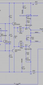
Bootstrapping the first EF would open the door to a wider range of candidates for Q12 and Q13, including low voltage types (usually high beta implies a thin base, which in turn reduces Vceo).
kind regards, jonathan
Just to let you know, I am still thinking about this. I have bootstrapped the 1st EF stage, and replaced the KSC3503/A1381 with BC547/557 small-signal transistors. Distortion at 200W, 20 kHz is improved by 60% from 0.005% to 0.002%. I am not seeing any small-signal stability issues.
As I noted to rsavas, I am lately seeing oscillation during my slew rate sims. It has vexed me, but I am finally understanding the mechanisms involved. I don't want to show THD results until I solve the slew oscillation problem.
the TL431's are compensated for heat, they won't provide the bias multiplier effect preventing thermal runaway. use a 3904 or KSC3503 mounted to the heat sink.
All of the BJTs that I suggested are still available for purchase in Japan, but it is relieving to know that the BC547/557 have improved performance.
Russell, adding base resistors to each cascoding device has sometimes resolved the cascode oscillations that I have experienced. Would this improve anything in your situation?
Alternatively, if your analysis of excessive loop delay is on target, would adding a shorter high-frequency feedback loop help?
i.e., 5~15pF capacitor from FCAS Top / FCAS Bottom to Q3 negative input.
kind regards, jonathan
Russell, adding base resistors to each cascoding device has sometimes resolved the cascode oscillations that I have experienced. Would this improve anything in your situation?
That was the first thing I thought to try, too. It didn't help. In fact, I still had slew-induced oscillation with the input cascodes removed entirely. Ultimately, the problem is trying to apply feedback to a dead transistor, because the amp is at its slew limit. Frankly, I'm surprised I haven't seen it before. I think I have just not pushed for this high a slew rate with this topology. With a conventional VAS, the compensation is its own feedback, so it takes care of itself.
Alternatively, if your analysis of excessive loop delay is on target, would adding a shorter high-frequency feedback loop help?
i.e., 5~15pF capacitor from FCAS Top / FCAS Bottom to Q3 negative input.
Yes, I tried this, too, and this did help, but it did not entirely cure it. Ultimately I put a Zoebel between the collectors of the input pair, to limit the slew rate a little, and make the transistor share a bit, and that was the cure. Did not seem to affect gain at audio or stability otherwise. I'll be posting the schematic and the new performance in a little while. So far, so good.
This is a lot easier now that I'm 57 than it was when I was 27, trying to make it all work without the an internet full of helpful experts.
the TL431's are compensated for heat, they won't provide the bias multiplier effect preventing thermal runaway. use a 3904 or KSC3503 mounted to the heat sink.
I am not sure what you are referring to, stocktrader. I am not setting output transistor bias with a TL431. Check out this link.
William Chater's "Bias control for power amplifiers," Revisited
Thanks, Pinnocchio.
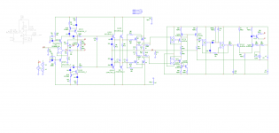
Folks may have noticed I've taken a bit of a break from the project. It was starting to interfere with my job. I'm still here. That oscillation problem is still the one on my plate, and I believe I have it solved. Zoebel between collectors of the input pair to reduce SR by about 10 to 20%.
The amplifier chassis are set to arrive this week from China. I've got a TEquipment cart waiting on me to sell my motorcycle, so I can pay for the order.
Thanks, Pinnocchio.
Folks may have noticed I've taken a bit of a break from the project. It was starting to interfere with my job. I'm still here. That oscillation problem is still the one on my plate, and I believe I have it solved. Zoebel between collectors of the input pair to reduce SR by about 10 to 20%.
The amplifier chassis are set to arrive this week from China. I've got a TEquipment cart waiting on me to sell my motorcycle, so I can pay for the order.
Hello RussellKinder, your design is just amazing!
Even if I, as a beginner, benefit from your articles.
You are on your way to success step by step. May your project go well.🙂
I have a question. Connect a capacitor in parallel with the base resistance of the driver and add a zero. Is it really possible to increase the available loop gain at 20Khz? Why do some netizens comment like this?
But it seems to only improve the high-frequency stability, and does not increase the amount of negative feedback at 20Khz.
Attachments

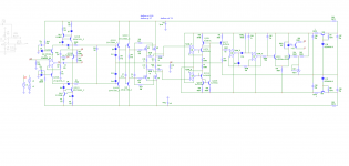
I studied and I liked Kurt's concept of autobias. I would propose some small changes, not to the concept but to the practical realization. For now, I only simulated it and in the next few days (weeks) I will build it. The amplifier is just an example, the autobias can be applied to any amplifier. Maybe someone has some remarks.
Attachments
I studied and I liked Kurt's concept of autobias. I would propose some small changes, not to the concept but to the practical realization. For now, I only simulated it and in the next few days (weeks) I will build it. The amplifier is just an example, the autobias can be applied to any amplifier. Maybe someone has some remarks.
Hi,
To be honest I would simply go ahead and try out Russell's SLABS (SOA Limit And Bias Servo) if I were you.
Here is Russell's SLABS schematic with POST #80.
The Autobias you're proposing appears to be identical to the Bias Servo part in SLABS in terms of principles of operation. However, the SLABS takes power transistors' collector current samples off a pair of current sampling resistors by the power amp's supply rails, instead of sensing across the emitter resistors, and that eliminated the need of an extra isolated split rail power supply that's needed in your proposal, as all power supplies SLABS needs are derived from the amp's power rails.
SLABS is also equipped with a start-up control that sets up the initial charge over the peak-hold capacitor as well as over the capacitor in the active LPF, this ensures a gentle and polite settle in of the bias current at power-on.
I put the SLABS to a compact 2"x2" layout in KiCAD, with Post #124
I afterwards made an all SMD layout that uses copper planes on the PCB as heatsink. The estimated thermal performance is more than adequate to handle the power dissipation. The PCB is so compact that with a 10cm x 10cm prototyping panel you can have four boards.


I'll soon upload the KiCAD files.
Last edited:
Indeed your pcb is very beautiful and compact. The reason I made these small changes was so that I didn't have to use extra power resistors to gather current information. Another reason was that the power supply was simpler. In my opinion, no special circuits are needed to discharge the capacitors. The way I drew them at the start, the optocoupler is blocked and starts to run late so that the idle current through the power transistors gradually increases. ic4 I think lm4562 and ic4 tl082 are enough. I think that having fewer parts, the pcb can be made even more compact. This time I also drew the power supply. It can be seen that the voltages are also obtained here from the power supply of the amplifier by bootstrap.
Attachments
- Home
- Amplifiers
- Solid State
- RK-Auto200W Amplifer