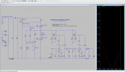
Good luck. I'm not sure exactly what ended up connected to what, but the magnitude and shape of the noise, and the fact that it persists after you move it somewhere else to measure, indicates the problem is caused by the power supply somehow or other not producing the correct full-wave rectified DC output.
My simulation doesn't reproduce the output waveform exactly, but I can see the same waveform as your output noise being generated in parts of the circuit so I have little doubt the problem is the diode connection somewhere.
Depending on what you did, the full secondary negative potential might have been applied to the filter capacitors. Just bear it in mind that they might have been damaged.
I'm not sure what's at fault, the supply I'm currently using is a standard four terminal bridge diode (pretty hard to connect that the wrong way) with CLC filter. The introduction of this supply has reduced the amount of hash on the output to listenable levels. As you pointed out your trace does not exactly match the output derived from my boards. I believe the difference is significant enough to look at other possibilities. My first port of call will be to connect one board to my bench supply and take a plot of the output and see where that leads me.
What software do you use to do the FFT on the wav files?
Regards
Greg
What software do you use to do the FFT on the wav files?
Regards
Greg
It's a free package called Audacity. It doesn't record 24bit in Windows due to liscensing but it will analyze one if you can record it elsewhere.
Are the available main CCS mA enough to ensure that the regulating part works properly after the load draw is deducted? There are tolerances in active parts. A prototype might just be OK and a copy might not if the current reserve margins are tight.
Yes, Greg has confirmed to me that the circuit currents and voltages are all close to expectations, including the shunt.
The main clue is the 50 Hz fundamental. This says to me the problem is off board as only 100 hz ripple should be found if the power supply was working properly.
The main clue is the 50 Hz fundamental. This says to me the problem is off board as only 100 hz ripple should be found if the power supply was working properly.
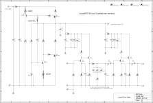
CrystalFET BOM rev. 13c11
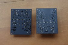
Added a reference photo of the assembled boards, and changed the default transformer from 2x15 VAC to and 2x18 VAC model.
2x15 V secondaries will work fine 97% of the time, but 2x18 is ironclad in that no amount of AC undervoltage is going to cause the regulator to drop out. The current draw of the circuit is so low that the extra voltage carries little penalty.
Basically, you can use whatever you feel comfortable with between 30-36 V total.
****
I'd also like to report that another 1.2a CrystalFET I built (post 182) with the internal power supply has no hum or noise problems, though the gain is reported to be a little lower than I anticipated. Seems more like 50-55 dB in reality, rather than the 55-60 dB the simulation keeps reporting.
Attachments
I finished my 1.2a boards.
First measurements indicate a good gain matching between the channels (<0.1dB) and the amplification at 1kHz is 60dB. RIAA conformance seems to be very good at the first sight (will be measured when I get my precise inverse-RIAA [< +/- 0.02dB] back from a friend).
Now i'll put it into an enclosure and do some listening 😀 Then I can also report on hum and noise performance.
kind regards, Daniel
Thanks for the update, especially for confirming the gain is 60 dB as simulated. That's very helpful to me.
RIAA I am pretty confident in, as long as your capacitors are close to 100 nF it will track closely. Looking forward to the hum/noise data though.
/R
RIAA I am pretty confident in, as long as your capacitors are close to 100 nF it will track closely. Looking forward to the hum/noise data though.
/R
So hey partsconnexion is selling some Plitron transformers dirt cheap which would be perfect for this project,
Plitron Transformers
see first item 5668-B2-00
Plitron Transformers
see first item 5668-B2-00
Bench note:
I had the opportunity to test what happens when the CrystalFET is undervolted. I was using a 2x15 VAC power transformer but since I'm on 100VAC line that gives 2x12.75 VAC for a V++ of about 36 V. The V+ needs to be at least 6 V below the V++ for the regulator to work, anything higher than that indicates the shunt regulator has run up against its limit.
It still regulates, just not very well. You'll see ripple of about 1 mV / -60 dB at the output. This translates to low level, audible hum at normal listening levels.
To solve, you can increase V++ (new power transformer) but it may be possible to instead just lower the V+ (by adjusting R20) until it moves out of the end zone and the voltage regulator kicks in again.
It should normally be possible to lower the V+ by 2-3 V (to say 29-31 V at TP1) without running into problems with the amplifier circuit. Basically the JFET drains should stay above 6 V. If that's the case, you'll be fine.
Confirming another small point: there are no audible thumps on turn on or off. There is a slow voltage waveform of about 50-200 mV max amplitude twice on turn on, and once on turn off, so you might see some woofer cone excursion even if you can't hear it.
All told pretty benign, but I recommend having the speakers muted before plugging in or unplugging the CrystalFET just to be on the safe side.
All told pretty benign, but I recommend having the speakers muted before plugging in or unplugging the CrystalFET just to be on the safe side.
I tend to design conservatively.
The CrystalFET power supply has a number of "seatbelts" designed to reduce absolute performance in the interests of operational stability. The NS (No Seatbelts) mod removes them.
You can try it non-destructively, just short over the following resistors: R12, R13, R15, R19, and R24.
The voltage regulation improves so much that the RC stages of R12 and R13 can be removed and still the overall PSRR at the output is better. If it works without crazy overshoot and other disobedience it should yield impressive results as the power supply impedance stays so much lower in the bass frequencies so there is less intermodulation/unwanted interaction between the input and output gain stages.
I will get around to trying this at some point, but posted it early so if someone out there is feeling adventurous ...
Attachments
R17 may need to be reduced to 22 ohms when R15 is shorted, you want to keep the current flowing through R17 above 25 mA.
So I gave it a shot...
With all five resistors shorted out, as shown in the photo, at first I was surprised at how little the sound changed. However, after listening to a couple of sides I came to the conclusion that this was overall a net negative change.
There is a little more emphasis and definition to the bass frequencies, but the midrange suffers. There is a harshness, or roughness there that there wasn't before and overall the details seem obscured.
I conclude that the RC stages R12 R13 are important for filtering out residual power supply noise, probably generated by the regulator itself. This makes even more sense when you remember that the phono stage circuit itself has zero to negative PSRR.
So, I removed the shorting jumpers over R12,13 and also R24 (that mosfet probably needs damping) but left R16 and R19 shorted. This is pretty much as I had it originally, but with Q5 and Q6 fully cranked up, with no emitter degeneration. The PSRR of the voltage regulator is improved by 22 dB at 100 Hz.
This state I will call "NS mod partial". I'm pretty happy with it. Base frequencies are tight and rhythmic, but the midrange is still smooth and musical. It seems quieter than ever, I could pick out more details of the harmonies &c than before.
More in a bit...
Attachments
Last edited:
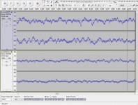
I measured the baseline output noise, inputs open, in exactly the same way as I did two months ago when I first finished the Crystalfet project.
On average, the noise floor has decreased 5-6 dB!
I'm certain this is not measurement error, as the conditions, levels, etc. are unchanged. It's possible, I suppose, that the filter caps or other components have broken in over time, I did not measure again before I started the mod. It is possible the circuit gain has changed, I didn't check that either.
However, from simulation, the lower noise on the output (and, it is presumed V+) is exactly what is expected from the improvements in the regulator performance. At some point the regulator gets so good that the output noise is dominated by the JFET noise, but it seems the original configuration at least was still defined by the V+ noise.
So, yes, I definitely recommend getting rid of what is R15 and R19 on the later schematics - the 47.5 ohms resistors on the emitters of Q5,6. (R16 and R15 were switched going to rev. 1.1->1.2)
Attachments
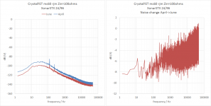
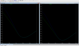
This is the PSRR at the V+ after R12 (V_input) and output according to LTSpice, but the simulation is only looking at the attenuation of nominal voltage signal at the V++, it doesn't consider noise generated internally within the regulator.
So while it shows 20 dB improvement across the board with the emitter resistors shorted (right plot), the measured output noise does not mirror this shape (with 100 dB change going to 10 kHz) because other components (mosfet noise, jfet noise, resistor noise...) contribute more at midrange frequencies than the V++ noise shown here. At least that's how I read this. Most of the improvement is expected at bass frequencies. That tendency at least I do measure, but it is less obvious than the simulation suggests.
So while it shows 20 dB improvement across the board with the emitter resistors shorted (right plot), the measured output noise does not mirror this shape (with 100 dB change going to 10 kHz) because other components (mosfet noise, jfet noise, resistor noise...) contribute more at midrange frequencies than the V++ noise shown here. At least that's how I read this. Most of the improvement is expected at bass frequencies. That tendency at least I do measure, but it is less obvious than the simulation suggests.
Attachments
There never were such resistors in SSLVs (like R15,R16) for the same reasons you discovered. Its a better shunt reg architectural transfer to your design now. Another helpful thing is more standing current that guards rails modulation THD better in such a reg. Alas, it leads to sinks. But its effectiveness depends on a particular load's dynamic current demands and in the presence of further rail filters or not. If C17 was 220u or higher and not 22u you could stop the ref noise in its root better BTW. This is a unity gain Vref and it is the main contributor since the semis don't amplify the ref. Then again maybe not the same effectiveness when there is a filter further down the rail.
Hi Salas,
I knew going in that the emitter resistors reduced the PSRR, but I thought the output would still be low enough to slip under the baseline noise of the amplifier itself. I spent too much of my time worried about power line harmonics rather than broadband noise...
I'm still wondering where the residual noise now originates: the amp itself, the regulator circuit, or the rectified power input. If it's the power input (on V++) then increasing C17 will help, definitely, but on the initial evidence at least it seems like most of it now originates at the JFETs, or effectively there.
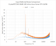
You can see in the plot below: the "bump" at 100 Hz is due to "power supply" noise originating upstream of the RC filter stage R12,13. The flat baseline up to 5 kHz, and rising section above 10 kHz is due to amplifier noise from the first and second JFET stages respectively.
Why does the JFET noise seem to decrease after the mod? Why does the power supply bump decrease just 3 dB when the simulation says the PSRR improves over 20 dB? I don't know, and it bothers me.
P.S. Input referred noise calculated assuming gain = 50 dB, my best available measured estimate but I don't have 100% confidence in. The name of the circuit is MC 60dB because 60 dB was the target.
I knew going in that the emitter resistors reduced the PSRR, but I thought the output would still be low enough to slip under the baseline noise of the amplifier itself. I spent too much of my time worried about power line harmonics rather than broadband noise...
I'm still wondering where the residual noise now originates: the amp itself, the regulator circuit, or the rectified power input. If it's the power input (on V++) then increasing C17 will help, definitely, but on the initial evidence at least it seems like most of it now originates at the JFETs, or effectively there.
You can see in the plot below: the "bump" at 100 Hz is due to "power supply" noise originating upstream of the RC filter stage R12,13. The flat baseline up to 5 kHz, and rising section above 10 kHz is due to amplifier noise from the first and second JFET stages respectively.
Why does the JFET noise seem to decrease after the mod? Why does the power supply bump decrease just 3 dB when the simulation says the PSRR improves over 20 dB? I don't know, and it bothers me.
P.S. Input referred noise calculated assuming gain = 50 dB, my best available measured estimate but I don't have 100% confidence in. The name of the circuit is MC 60dB because 60 dB was the target.
Attachments
Last edited:
At your now measured "blue grass" level I think most of the noise is the self noise of the audio circuit. Some 100Hz maybe sneaks through the GND route even. There is a wide lab measurement loop area to consider. Or its not suppressed enough in the high impedance Norton Vref. A higher C17 would show about that hypothesis. The bass region SNR picture is much sensitive because of the RIAA boost in that area. When not having a throughout differential circuit but an SE with no PSRR every common mode noise will still can be picked down to a practical limit of controlling it buildwise. Your error amp (BD139) could benefit from a CCS load to increase the open loop gain by the way. But you could already be at your diminishing returns threshold. You will judge that. When all things get well proportioned there is a nicely melodic well detailed but natural sound emerging from the combination of such a reg and an SE JFET high gain preamp. When at that point, you know it. You are probably already there so it could be bit more to squeeze or it will start tightening up distastefully by further technical performance mods. Your baseline noise curve and harmonic noise needles (June red curve in dB) look more than adequate by now for TT replay given the JFET types involved.
- Status
- Not open for further replies.
- Home
- Source & Line
- Analogue Source
- RJM Audio Crystal P jfet phono preamplifier | development thread