Thanks for pointing that out. I originally had 100 uF as being the minimum, but found the frequency response worked out a little better with 220 uF with R5 tuned appropriately, and I had these parts already. If you use 100 uF, make R5 about 33k.
Never use the values in the Eagle-generated schematic for an actual build. Always use the BOM list for your reference.
1. Mistakes persist longer on the schematic, since I don't use these for reference myself.
2. Eagle doesn't have every part, so I sometimes make substitutes as needed just to get the right board layout.
3. I often round Eagle parts values to closest 5% like 330 ohms, while the BOM gives the actual available resistance in the Koa Speer 1% ML resistors, 332 ohms, for example.
Does it ever matter if the resistor is 330 or 332 ohms? No. Koa make both 5% and 1% series values, I just decided to stick to 1% values for consistency... so you'll (almost) always see me write 22.1k in the BOM rather than 22k, but of course you can use 22k or 22.1k from whatever manufacturer you want.
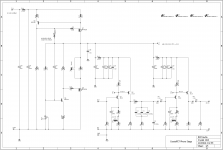
Attachments
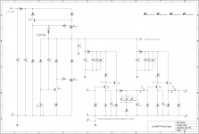
One thing though, how did you obtain the 28.7k value?
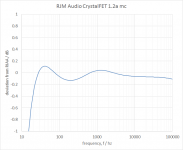
Using trial and error, comparing the TLSpice frequency response against the standard RIAA curve.
As I hinted at in the previous post, R5 adjusts the low frequency boost and can be used to partially compensate for the additional bass rolloff caused by C1,7.
Attachments
Don't ask - it's been a rough couple of weeks.
rev 1.3c boards are back from the fab. I sent the job to pcbway this time, I have to say I have no complaints. It's amazing they can offer the price the do on such small jobs.
So anyhow, all previously ordered kits / parts will be shipped out tomorrow. Sorry for the various delays.
I'm going to be busy for a while and I'm out of matched J113 so I'm only going to be able to ship boards for a bit. Jfets and kits will have to wait until mid-May.
Attachments

New BOM ... because Fairchild J113 in through hole TO-92 packages are available off the shelf at Mouser p/n 512-J113.
For some reason earlier I thought they were discontinued.
Also added a note that R1 may need to be supplemented with addition cartridge loading.
While you can remove R1 and replace it, it is easier I think to just leave it as 47k and add load resistors as needed in parallel.
The load resistors can be attached to the RCA jack (what I find easiest), or you can add a separate little board with resistors, capacitors and DIP switches.
What I find the problem there is you spend time making this neat little board with 3-4 different options then you get a new cart which needs something else again. If you frequently switch cartridges though it can be a welcome feature.
Attachments
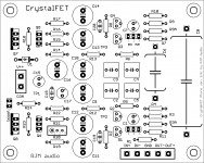
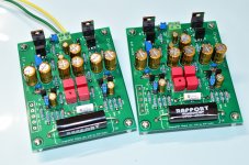
To check everything, I built myself one of the 1.3c kits.
All good. Perfect, actually.
The completed and tested boards in the photo are available. pm me if interested.
All good. Perfect, actually.
The completed and tested boards in the photo are available. pm me if interested.
Attachments
Last edited:
Is there any disadvantage of using one 0.1uf in the position of three cap c2 c3 c4? (Those three are just parallel and the sum is around 0.1uf.)
All done, I have rev1.2a board.
I use rev1.3c schematic and BOM with some modification.
I use 0.1uf for c2 c3 and c4.
The rev1.3c would be very versatile, switching between MM and MC easily.
Sound is very good, well balance and natural sound.
Thank Richard. 😀
I use rev1.3c schematic and BOM with some modification.
I use 0.1uf for c2 c3 and c4.
The rev1.3c would be very versatile, switching between MM and MC easily.
Sound is very good, well balance and natural sound.
Thank Richard. 😀
Attachments
Yes I have enough gain for my ss preamp and I think even the 30db gain in rev1.2a should be enough for my tube preamp.
@rjm. Forgot to inform you I had received the boards a few days back. Now just waiting for the resistors and capacitor to be delivered.
Sent from my AO5510 using Tapatalk
Sent from my AO5510 using Tapatalk
- Status
- Not open for further replies.
- Home
- Source & Line
- Analogue Source
- RJM Audio Crystal P jfet phono preamplifier | development thread