Gerhard, I stopped reading after I realized I don't understand your design goal. First you are saying you are interested in the LF noise, then you want to push the design to 100MHz. Do you have a clear set of design requirements? Or at least a clear application for this amplifier, that could drive the design requirements?
Looking only at the schematics, the abundence of high value electrolytics is a definite turn off, but that's me.
While nobody is denying the appetite for oscillation of the CS JFET, and you are explaining well the possible oscillation mechanism, have you seen #1718 in this thread https://www.diyaudio.com/forums/ana...ra-low-noise-mc-head-amp-172.html#post5977292 ? It is not as bad as you put it, in particular if you don't want to eat the cake and have it too. I'm still ready to show you the stable noise performance of 64xBF862 in parallel, running close to Idss (total of some 0.75 amps of drain current): 0.15nV/rtHz. With individual 1uH inductors on the gates.
Gerhard, I don't like C2 until you have source with dc component. Sorry
What is to dislike with a WIMA 10u PP?
And for a measurement amplifier, nearly all signal sources have DC.
I have a not so nice coal brick where I forgot to remove the jumper
over the wet slug tantalum on the input when measuring the noise of
some 18650 Lithium cells. OK, the wet slug tantalum survived, the 20
parallel op amps did not, including the board. At the price of the
tantalum, it could have turned out worse.
Even for an amplifier with DC-less input at less than Idss, you could not do
without a capacitor. In this case it would not be PP but a fat electrolytic at the source.
Or you would have to accept the source resistor as a noise generator in series
to the input.
Last edited:
You mentioned that low lf noise is desired, but with 10u you will amplify noise of R11 at lf. I may be wrong, I don't know what lf is
photo cell from Scott?you could not do without a capacitor.
Are they in the same style milled Al brick?
No, the Al brick is only for avoiding the mains frequency and harmonics spuriae.
You mentioned that low lf noise is desired, but with 10u you will amplify noise of R11 at lf. I may be wrong, I don't know what lf is
photo cell from Scott?
No, it does not amplify the noise of R11, it does short the noise of R11 through the
source impedance, the larger R11, the easier.
And the source impedance must be _very_ small, or else a 200 pV/rtHz amplifier
would be pearls before swine.
10 Meg delivers 406 nV/rt Hz, do you see any trace of it in the noise plot?
100 Meg would be even easier, not worse. Yes, that's against the belly feeling.
But it is mismatching at work.
The real problem is the time constant.
Input RC must not be selected for f-3dB. At f-3dB R and Xc have the same value.
Oh, really at ~ -6 dB.
For effective shorting, Xc must be _much_ smaller than R.
As in 10uF vs. 10 Meg.
The revenge is that it takes an eternal time to find a stable quiescent condition.
And if the input DC changes, you go back to start. I have a window comparator
that checks the operating point and if we are outside the window, R11 is shorted
so things develop faster with just 50K bias impedance. That used to be an
analogue switch, but now it's a reed contact. I didn't trust the residual currents.
It's 4 am here,
have a good night.
Gerhard
What is to dislike with a WIMA 10u PP? .
Can be an efficient antenna.
100 Meg would be even easier, not worse. Yes, that's against the belly feeling.
With 100Megs and 16 JFETS, the input current noise will bite you badly. According to the CPH3910 data sheet, IGSS is max 1nA @Vds=10V per JFET, which is a total of 44fA/rtHz noise. Multiplied by 100Mohm, that’s 4.4nV/rtHz, goodbye noise performance.
You may get along with 10Mohm, limiting Vds of the JFETs by cascoding to 2-3V (which is what I always do) and hoping 1nA is actually less in practice, but even so, 10Mohm for 16 JFETs is a rather tall order.
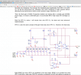
No, it's not goodbye. Not at all. 99.9999% of the shot current would not flow through
the 100 Meg but through the capacitor and the low generator impedance.
It would be shorted like the resistors own thermal noise.
To prove this, I have forced your 44 fA/rt Hz with a VCCS fed from the 1nV/rtHz thermal
noise of a 60 Ohm resistor. No effect.
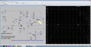
I have also changed the 10u input capacitor to 10n to show why it is needed so large.
Noise explodes below 5 KHz, while the passband still starts at a few Hz, no change.
The comment in the picture should read "n/f = 1e6".
With raw Vcc = 5V3 and R5 as an excuse for a current source, there won't be much
voltage left for ionization current from the channel.
Attachments
Last edited:
No, it's not goodbye. Not at all. 99.9999% of the shot current would not flow through
the 100 Meg but through the capacitor and the low generator impedance.
It would be shorted like the resistors own thermal noise.
Absolutely, no doubt about that, but then again, what do you want to do/achieve? If the input current noise doesn’t matter, since the source impedance is very low, then why bothering with JFETs after all? JFETs are used for higher source impedances, precisely for their low input current noise.
That is absolutely correct, but capacitor is in series with source impedance. With R62=1M curves will shift to the left (higher resistance = lower noise current)No, it does not amplify the noise of R11, it does short the noise of R11 through the
source impedance,
Attachments

Gerhard, I stopped reading after I realized I don't understand your design goal. First you are saying you are interested in the LF noise, then you want to push the design to 100MHz. Do you have a clear set of design requirements? Or at least a clear application for this amplifier, that could drive the design requirements?
Looking only at the schematics, the abundence of high value electrolytics is a definite turn off, but that's me.
While nobody is denying the appetite for oscillation of the CS JFET, and you are explaining well the possible oscillation mechanism, have you seen #1718 in this thread https://www.diyaudio.com/forums/ana...ra-low-noise-mc-head-amp-172.html#post5977292 ? It is not as bad as you put it, in particular if you don't want to eat the cake and have it too. I'm still ready to show you the stable noise performance of 64xBF862 in parallel, running close to Idss (total of some 0.75 amps of drain current): 0.15nV/rtHz. With individual 1uH inductors on the gates.
Now that the Gerbers are transferred,
the design goal is simple: I want a measurement amplifier with at least 1 MHz bandwidth,
but when I'm given 100 MHz for free, I won't object it. It has built-in BW limitation anyway
for scoping around at low frequencies. The voltage noise should be low enough that I should
not need to compute its influence away with the majority of the DUTs. With really
low source impedance I get by with my 20xADA4898 amplifier which is stable, low
voltage noise, is fast enough, but its noise current @ > 50 Ohm is just so.
Although 50 Ohms source is pearls before swine at 220 pV voltage noise, it starts to
hurt when I want to dig deeper with cross correlation, because that takes 2 equal
amplifiers and the noise current of both flows through the DUT, creating a noise
voltage component that won't average away. The normal voltage noise of the
amplifiers will go away with enough averaging.
Also, the not-so-high input impedance of the 20 op amps will require a 4700 uF
wet slug tantalum in the input (with luck 4700 uF ALU) because with only 100U foil
as in my first attempt, the noise will rise sharply below 100 Hz.
That large capacitor is dangerous for the input transistors of the op amps, when
suddenly connecting 12V for example or shorting the precharged input. The current
version has protection relays, but the sequencing is not foolproof.
And people who want to nag me claim that I ignore the noise current, which is wrong.
So a FET version does away with all those problems, maybe it costs some 1/f. But then,
cross corr. brings easily 20-30 dB which makes up for it. See Fred Walls battery noise
measurements @ NIST, Boulder, Co. Cross corr. also allows to reduce the number
of FETs greatly.
And that it does not happen to oscillate does not mean it cannot. The vector network
analyzer is cruel enough to uncover every such tendency. That's good.
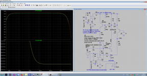
And your 64xBF862 is probably not a relative of HPS5.1? See the sim below. The phase
of the real part flips by 180° between 600 KHz and 60 MHz. And with series inductors
you cannot heal a negative real part, the best you can hope for is that the L decreases
the resonant frequency below the negative real part zone. Which says nothing about
peaking etc.
It's not that this is a esp. bad case, the amplifier from fig. 3.34 in Art Of Electronics
and some of mine behave exactly the same way as soon as the fb loop is closed.
For a measurement tool, I cannot accept that.
As Frank'nfurther said: I'll remove the cause, and not the symptom.
And it's not that there are oh so many high value capacitors. There is one for
VCC and VEE; they could be made smaller with a cap multiplier, but that would
expose us to the 1/f behaviour of the multiplier. Then there is a cap that
slows down the operating point settling so that it does not counteract gain at
100 mHz and avoids motor boating.
100uF seem to be enough. The only high value capacitor in the signal path
is the input to the cascode stage, which is hopefully a very low impedance point.
Cheers,
Gerhard
Attachments
Last edited:
Now that the Gerbers are transferred,
the design goal is simple: I want a measurement amplifier with at least 1 MHz bandwidth,
but when I'm given 100 MHz for free, I won't object it. It has built-in BW limitation anyway
for scoping around at low frequencies. The voltage noise should be low enough that I should
not need to compute its influence away with the majority of the DUTs. With really
low source impedance I get by with my 20xADA4898 amplifier which is stable, low
voltage noise, is fast enough, but its noise current @ > 50 Ohm is just so.
Although 50 Ohms source is pearls before swine at 220 pV voltage noise, it starts to
hurt when I want to dig deeper with cross correlation, because that takes 2 equal
amplifiers and the noise current of both flows through the DUT, creating a noise
voltage component that won't average away. The normal voltage noise of the
amplifiers will go away with enough averaging.
Also, the not-so-high input impedance of the 20 op amps will require a 4700 uF
wet slug tantalum in the input (with luck 4700 uF ALU) because with only 100U foil
as in my first attempt, the noise will rise sharply below 100 Hz.
That large capacitor is dangerous for the input transistors of the op amps, when
suddenly connecting 12V for example or shorting the precharged input. The current
version has protection relays, but the sequencing is not foolproof.
And people who want to nag me claim that I ignore the noise current, which is wrong.
So a FET version does away with all those problems, maybe it costs some 1/f. But then,
cross corr. brings easily 20-30 dB which makes up for it. See Fred Walls battery noise
measurements @ NIST, Boulder, Co. Cross corr. also allows to reduce the number
of FETs greatly.
And that it does not happen to oscillate does not mean it cannot. The vector network
analyzer is cruel enough to uncover every such tendency. That's good.
And your 64xBF862 is probably not a relative of HPS5.1? See the sim below. The phase
of the real part flips by 180° between 600 KHz and 60 MHz. And with series inductors
you cannot heal a negative real part, the best you can hope for is that the L decreases
the resonant frequency below the negative real part zone. Which says nothing about
peaking etc.
It's not that this is a esp. bad case, the amplifier from fig. 3.34 in Art Of Electronics
and some of mine behave exactly the same way as soon as the fb loop is closed.
For a measurement tool, I cannot accept that.
As Frank'nfurther said: I'll remove the cause, and not the symptom.
And it's not that there are oh so many high value capacitors. There is one for
VCC and VEE; they could be made smaller with a cap multiplier, but that would
expose us to the 1/f behaviour of the multiplier. Then there is a cap that
slows down the operating point settling so that it does not counteract gain at
100 mHz and avoids motor boating.
100uF seem to be enough. The only high value capacitor in the signal path
is the input to the cascode stage, which is hopefully a very low impedance point.
Cheers,
Gerhard
No, it is not HPS5.1, more like HPS 1.0 (which is pretty much the Dennis Collin approach) and a rather low closed loop bandwidth of about 100KHz (at x1000 closed loop gain). You would of course know that the JFET models in Spice are extremely crude, both in the small and large signal domains, lots of phenomena are simply not modeled (subthreshold conduction, noise other than channel conduction, Cgd variation, short channel effects, etc...). So as much as I don't trust the regular free models for any semi device including op amps macro models, I trust JFET models even less that the average.
Otherwise, you appear to have changed your goals quite a bit; some time ago you were looking at something to measure battery noise, therefore you did the 20x ADA4898; at that time, I mentioned the input current noise but you said it did not matter for the application you had in mind (true). I suggested a FET approach (to support higher source impedances) and you rejected the idea on the same grounds of stability. Nevertheless, for battery noise measurements, you would not need more than say 10KHz bandwidth, which even for x1000 gain would allow you to compensate the loop well under any critical frequencies where oscillations may occur (worst case). Of course, 100MHz closed loop bandwidth for a feedback amplifier with high closed loop gain (>100) is impossible, so your "no feedback" approach has ultimately no competitor, anyway.
One last thing, you really don't care about the gain precision and drift? A no feedback approach can obviously not have much of gain stability. You cannot design for a precise gain, it's all about trimming (or measuring it and using the value as is, until you may need to replace a JFET).
Last edited:
No, it is not HPS5.1, more like HPS 1.0 (which is pretty much the Dennis Collin approach) and a rather low closed loop bandwidth of about 100KHz (at x1000 closed loop gain). You would of course know that the JFET models in Spice are extremely crude, both in the small and large signal domains, lots of phenomena are simply not modeled (subthreshold conduction, noise other than channel conduction, Cgd variation, short channel effects, etc...). So as much as I don't trust the regular free models for any semi device including op amps macro models, I trust JFET models even less that the average.
I could use ADS or Microwave Office, but that would cost me good will points
with day-time customer. You can currently get a free 3-month license of full ADS.
officially for Corona home office work, but probably more to get you on the hook.
Otherwise, you appear to have changed your goals quite a bit; some time ago you were looking at something to measure battery noise, therefore you did the 20x ADA4898; at that time, I mentioned the input current noise but you said it did not matter for the application you had in mind (true). I suggested a FET approach (to support higher source impedances) and you rejected the idea on the same grounds of stability.
Batteries are boring, now that I have duplicated Fred Walls' measurements with
parts I can actually buy. Unnamed parts that he has in his drawer at NIST don't
help me much. Yes, with cross correlation he is still 10 dB better than me, in spite
of his simple preamp.
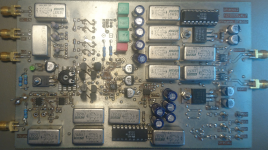
The really interesting thing for me is phase noise of oscillators and geophysics.
Pic below is a phase noise mix down head, PLL controller and FET amplifier with
8 FETs and space for some more. OK, it's differential, so it only performs as 2 pcs.
2SK389. It's inspired by a design from Charles Wenzel, the king of crystal oscillators.
Two-sided Eurocard 160*100mm, home etched.
Nevertheless, for battery noise measurements, you would not need more than say 10KHz bandwidth, which even for x1000 gain would allow you to compensate the loop well under any critical frequencies where oscillations may occur (worst case). Of course, 100MHz closed loop bandwidth for a feedback amplifier with high closed loop gain (>100) is impossible, so your "no feedback" approach has ultimately no competitor, anyway.
Batteries are needed just as a prerequisite for lab use. I cannot shoot them into orbit.
I need 1 MHz . This is already a step backwards, phase noise plots usually
go to 10 MHz. So, the customers still can be proud on their E5052B and the new
300K€ R&S phase noise spectrum analyzer.
I can get the FET amp stable with 1 MHz BW at least in simulation, but that is
no final success as the ultra fast op amps wreck the 1/f behaviour. The 30 dB gain
of the JFETs are quickly used up and do not mask the op amp 1/f noise at low
frequencies.
One last thing, you really don't care about the gain precision and drift? A no feedback approach can obviously not have much of gain stability. You cannot design for a precise gain, it's all about trimming (or measuring it and using the value as is, until you may need to replace a JFET).
I am the one with ".temp 20 40 60" in his simulations. The pos. and the neg. TC
of the JFET seem to cancel nicely for the small signal FETs. Interfet IF3602 with its
different operating points/environment has a gain error of 0.5 dB / 10°C, not so nice.
But I have a heater controller to keep it at 40°C.
I could use ADS or Microwave Office, but that would cost me good will points
with day-time customer. You can currently get a free 3-month license of full ADS.
officially for Corona home office work, but probably more to get you on the hook.
Otherwise, you appear to have changed your goals quite a bit; some time ago you were looking at something to measure battery noise, therefore you did the 20x ADA4898; at that time, I mentioned the input current noise but you said it did not matter for the application you had in mind (true). I suggested a FET approach (to support higher source impedances) and you rejected the idea on the same grounds of stability.
Batteries are boring, now that I have duplicated Fred Walls' measurements with
parts I can actually buy. Unnamed parts that he has in his drawer at NIST don't
help me much. Yes, with cross correlation he is still 10 dB better than me, in spite
of his simple preamp.
The really interesting thing for me is phase noise of oscillators and geophysics.
Pic below is a phase noise mix down head, PLL controller and FET amplifier with
8 FETs and space for some more. OK, it's differential, so it only performs as 2 pcs.
2SK389. It's inspired by a design from Charles Wenzel, the king of crystal oscillators.
Two-sided Eurocard 160*100mm, home etched.
Nevertheless, for battery noise measurements, you would not need more than say 10KHz bandwidth, which even for x1000 gain would allow you to compensate the loop well under any critical frequencies where oscillations may occur (worst case). Of course, 100MHz closed loop bandwidth for a feedback amplifier with high closed loop gain (>100) is impossible, so your "no feedback" approach has ultimately no competitor, anyway.
Batteries are needed just as a prerequisite for lab use. I cannot shoot them into orbit.
I need 1 MHz . This is already a step backwards, phase noise plots usually
go to 10 MHz. So, the customers still can be proud on their E5052B and the new
300K€ R&S phase noise spectrum analyzer.
I can get the FET amp stable with 1 MHz BW at least in simulation, but that is
no final success as the ultra fast op amps wreck the 1/f behaviour. The 30 dB gain
of the JFETs are quickly used up and do not mask the op amp 1/f noise at low
frequencies.
One last thing, you really don't care about the gain precision and drift? A no feedback approach can obviously not have much of gain stability. You cannot design for a precise gain, it's all about trimming (or measuring it and using the value as is, until you may need to replace a JFET).
I am the one with ".temp 20 40 60" in his simulations. The pos. and the neg. TC
of the JFET seem to cancel nicely for the small signal FETs. Interfet IF3602 with its
different operating points/environment has a gain error of 0.5 dB / 10°C, not so nice.
But I have a heater controller to keep it at 40°C.
Attachments
Last edited:

Gerhard, not sure if it's my colour vision but congratulation on finding the least legible colour choice on the forum 🙂
I have a question on
This confuses me as batteries are everywhere in orbit. You can't operate without then unless you have a nuclear power source which REALLY gets the launch guys twitchy 🙂.
I have a question on
Batteries are needed just as a prerequisite for lab use. I cannot shoot them into orbit.
This confuses me as batteries are everywhere in orbit. You can't operate without then unless you have a nuclear power source which REALLY gets the launch guys twitchy 🙂.
you did answer too early, I was still experimenting. 😀
That is then a project of its own. Alone the proof that it does not gas out!
I had to use the power that was offered. And the closer you come to the
primary supply, the more they watch you.
That is then a project of its own. Alone the proof that it does not gas out!
I had to use the power that was offered. And the closer you come to the
primary supply, the more they watch you.
Last edited:
- Home
- Source & Line
- Analogue Source
- Richard Lee's Ultra low Noise MC Head Amp