What loops, Hans? Are you suggesting to keep cable shield and MA box float?
As a matter of fact, your drawing shows exactly your current situation !
Will further react later tomorrow, quite busy at the moment.
Hans
This discussion has piqued my curiousity to actually measure how much 50Hz pickup there is around the living room. I assume calibrated tools for this are usually quite pricy and an old MC cartridge connected to a 60dB preamp to get relative measurements will probably do the job?
In UK the presence of ring mains always means you are inside a loop of copper wire but this house predates electricity so the retrofit and subsequent rewires will I suspect have cut some corners. Feed is overhead cables. The garden backs onto a field, so I suspect that, for **** value measurements sitting down there with the DUT on the picnic table might be the lowest for H field.
Not that any of this is audible of course, even with my silliest cartridges...
Bill, do it. It will be enormously satisfying to have your own data measured in your own home. Even if many naysayers petulantly explain why your results are not generalizable -- so what? You measured your house with the most hum-sensitive audio instrument you're likely to ever use in real world practice. If it detects nothing: smile and relax. If it detects hum: either change something or prepare to live with hum.
In a building riddled with mains cabling that's not shielded will see about a substantial fraction of the mains rms voltage in many places. The stray field is roughly the average of the 2 or 3 wires, unless there's grounded central heating pipework to reduce it, or outside masonry walls which are damp/conductive and thus at ground.
Mains pickup will be related to the self-capacitance of the circuit element involved - which is the capacitance to the surroundings basically.
Any circuit at mains earth potential provides a path for pickup to flow back to ground.
For instance a short piece of unshielded cable might have several pF to the surroundings, and if those surroundings are on average 30Vrms (quite possible), that's a current of several 10's of nV flowing to earth from the cable. In a 47k circuit that's of the order of a few mV of pickup. In a low impedance circuit, its much less.
If mains cabling was always shielded we'd never experience mains hum. If all mains wiring was balanced 2-phase or 3-phase most of the voltage would cancel out reducing hum by a large factor.
Shielded cable is more expensive and harder to work with, which is why its not often used for mains, but frankly that's a poor excuse as a shielded mains cable is far safer in the event it gets cut. Some outdoor cabling is armoured and shielded.
Last edited:
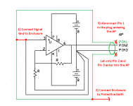
Dimitri, this is what I meant.
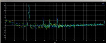
First set is for balanced connection, second set is for balanced connection with pin 1 lifted (measurement amp box is connected with PE). Scans were made within couple hours time period (fuse box and power entry to the house in 10 feet, heating system, washer/dryer switched on and off), cables and measurement box were fixed in the same position with 3M tape.
Sorry Hans, no improvement
Attachments
Last edited:
First set is for balanced connection, second set is for balanced connection with pin 1 lifted (measurement amp box is connected with PE). Scans were made within couple hours time period (fuse box and power entry to the house in 10 feet, heating system, washer/dryer switched on and off), cables and measurement box were fixed in the same position with 3M tape.
Sorry Hans, no improvement
Thank you for trying, this helps in building experience on the subject.
There is a slight improvement in the 60Hz component, but I agree this is not the sort of improvement that makes the difference I was hoping for.
Obviously you suffer from the same sort of magnetic induction as Syn08, so hopefully the mumetal box you have planned to use will make a difference.
Hans
P.s. you did not mention it, but may I assume that you had the signal gnd connected to the enclosure ?
yes, i haveI assume that you had the signal gnd connected to the enclosure ?
yes, i have
Thank you.
This brings me again to the question, in how far a true differential setup will make the difference.
With two equal halves, both equally oriented, magnetic induction will cause pollution of the same polarity and magnitude in those halves that can be removed in the Diff to SE conversion.
This must be one of the reasons why my spectra are so much cleaner.
Hans
Dimitri,
This posting shows a possible solution for your pollution problem with seemingly great effect.
My version of the G = 1000 low noise measurement amp (for Ikoflexer).
Hans
This posting shows a possible solution for your pollution problem with seemingly great effect.
My version of the G = 1000 low noise measurement amp (for Ikoflexer).
Hans
this is all on the AD797. Same theory as my 2 stage phono pre with low noise npn transistor up front. what is the function of the opa2134?
Dimitri,
This posting shows a possible solution for your pollution problem with seemingly great effect.
My version of the G = 1000 low noise measurement amp (for Ikoflexer).
Hans
Box in box is a classic, been there, done that, if you take a look at that quoted mumetal shielding it also implements this concept (two concentric layers, only much more effective due to the material nature).
To my experience double boxing in what are actually "Duraglit" boxes (thin steel sheet) is less effective than Faraday shielding.
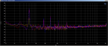
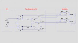
Wanting to satisfy my curiosity to what extent a Differential topology has the ability to suppress EMF radiation, I used the set-up in the image below with my MC cart connected, but also with a 1R short instead of the Cart.
The upper line is full SE and the other line fully Differential before being converted to SE.
The Diff to SE converter with high precision resistors has ca. 60dB CMRR.
Connection from HA to MA was through a RCA interlink cut in two 45cm halves, both open ends soldered to the HA.
RCA connectors at the other side plugged into the MA, thus giving exactly the same conditions for both lines.
MA connected to the scope with 2 equal 50R coax cables.
Now spectra generated through both topologies could be recorded simultaneously, taking into account that the SE line has 6dB less gain.
Electro Magnetic pollution was generated with a Power Drilling machine at relatively close distance to the to the HA. When increasing the distance to the HA, pollution decreased, showing that it was indeed EMF pollution.
What I measured with this relatively simple test, was a rejection of pollution of between 10dB and 15dB in favour of the Differential setup.
Hans
Attachments
P.S. I expect the Electro Magnetic pollution field that Syn08 and Dimitri are experiencing, to be spatially more homogeneous around the DUT than just a simple drilling machine.
If true, a differential topology could even do a better CMRR job.
Hans
If true, a differential topology could even do a better CMRR job.
Hans
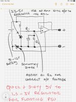
I’ve had one or two messages about powering the battery versions of the head amps off other than a 1.5 or 3 V battery.
Here is a circuit concept you can try. No details - you will need to do that yourself but I’m sure there are others here who can help with that.
Use an opamp with a common mode input range that includes the -ve rail. If not, use a Schottky diode in the opamp -ve rail as shown.
Make sure you mount the PSU and the battery in a shielded box to prevent capacitive coupling getting onto the PSU rails. Importantly, when the head amp is active, the battery charging circuit must be completely disconnected from the battery - use a switch that can break both the -ve and +ve rails between the charger and the battery (DPDT type).
Attachments
FWIW I just checked the higher-gain ZTX689B and estimate its rbb' to be 5.5Ω based on measurements in a test circuit that shows 1.75Ω for the ZTX851.
(hfe 500 minimum)
A Low Noise Balanced Input Moving Coil Preamp Using the ZTX851 - Page 50 - Pro Audio Design Forum
I have found, since 2016, that the ZTX851 are very consistent noise performers and not that difficult to Vbe match. A Low Noise Balanced Input Moving Coil Preamp Using the ZTX851 - Pro Audio Design Forum
The ZTX689B would be excellent for higher source impedance mic preamps or where bias current is a concern.
Last edited:
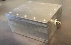
My latest low noise instrumentation amplifier.
- JFET based (8 in parallel, yes Gerhard, is rock solid stable 😀)
- 0.3Hz to 1.8MHz 3dB bandwidth
- 60.02dB gain
- 0.42nV/rtHz
- 1/f noise corner frequency is 100-150Hz
- needs +/-12V, takes 16mA/10mA so can use batteries
- Onboard ultra low noise LDO regulators
- encased in an aluminum block, 20mm thick walls, 15mm thick lid, about half a kilo of metal
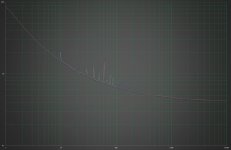
Noise plot is attached, Y scale is in nV/rtHz, X axis in Hz. Noise is higher than the previous version (0.32nV/rtHz) but this can be fed by 2 1.3Ah lead-acid cells. The 60Hz harmonic component is now at 1.5nV equivalent at the input, intermodulation products are still visible.
Can't do better in my allegedly EM polluted environment. Note that a cell phone or drill has absolutely no effect, the thick aluminum block shields perfectly everything that goes over 100Hz.
- JFET based (8 in parallel, yes Gerhard, is rock solid stable 😀)
- 0.3Hz to 1.8MHz 3dB bandwidth
- 60.02dB gain
- 0.42nV/rtHz
- 1/f noise corner frequency is 100-150Hz
- needs +/-12V, takes 16mA/10mA so can use batteries
- Onboard ultra low noise LDO regulators
- encased in an aluminum block, 20mm thick walls, 15mm thick lid, about half a kilo of metal
Noise plot is attached, Y scale is in nV/rtHz, X axis in Hz. Noise is higher than the previous version (0.32nV/rtHz) but this can be fed by 2 1.3Ah lead-acid cells. The 60Hz harmonic component is now at 1.5nV equivalent at the input, intermodulation products are still visible.
Can't do better in my allegedly EM polluted environment. Note that a cell phone or drill has absolutely no effect, the thick aluminum block shields perfectly everything that goes over 100Hz.
Attachments

I try to not have hateful envy in my heart for people with their own mills, but often come up short of true peace. Gotta work on that more.
Much thanks, as always,
Chris
Much thanks, as always,
Chris
My latest low noise instrumentation amplifier.
- JFET based (8 in parallel, yes Gerhard, is rock solid stable 😀)
- 0.3Hz to 1.8MHz 3dB bandwidth
- 60.02dB gain
- 0.42nV/rtHz
- 1/f noise corner frequency is 100-150Hz
- needs +/-12V, takes 16mA/10mA so can use batteries
- Onboard ultra low noise LDO regulators
- encased in an aluminum block, 20mm thick walls, 15mm thick lid, about half a kilo of metal
Noise plot is attached, Y scale is in nV/rtHz, X axis in Hz. Noise is higher than the previous version (0.32nV/rtHz) but this can be fed by 2 1.3Ah lead-acid cells. The 60Hz harmonic component is now at 1.5nV equivalent at the input, intermodulation products are still visible.
Can't do better in my allegedly EM polluted environment. Note that a cell phone or drill has absolutely no effect, the thick aluminum block shields perfectly everything that goes over 100Hz.
Very impressive!
- Home
- Source & Line
- Analogue Source
- Richard Lee's Ultra low Noise MC Head Amp